Roof Solar Off Switch | RV Mods
Our View did not come with a method to easily isolate the rooftop solar panels from the coach. During the times when I wanted to ensure the solar was not attempting to push current into the batteries – puttering around in the battery box, attempting to quantify the amount of load a system was pulling, or closing up the coach for the winter – I had to resort to climbing up onto the roof and pulling the plugs on the two panels. Ok, not a big deal when the roof is dry, but a whole different story when the roof is ice or frost covered! One winter, as I was sliding back to the rear of the motorhome with no control of my trajectory and potential impending doom, I started thinking … “there must be a better way!”
I decided that “better way” was to install an in-coach switch in the power line coming from the roof. There isn’t a good looking place to install the switch beside the solar controller, so it is hidden under the bed near the Truma hot water heater.
This is the switch I chose:
I Litton battery disconnect switch
The new circuit will usually see less than 20 amps from our four 100 watt panels, but I used #10 / 30 amp wire to give plenty of margin and to match the controller’s rating. (The Zamp solar kit that is supplied to Winnebago uses #8 / 40 amp wire, to cater for higher current systems that some RVs install.) In addition, the current rating on the switch itself is more than plenty for the loads that will be routinely seen.
This drawing shows how the switch was wired up (only the input side of the controller is shown) - the red wires are the only addition to the Winnebago setup:
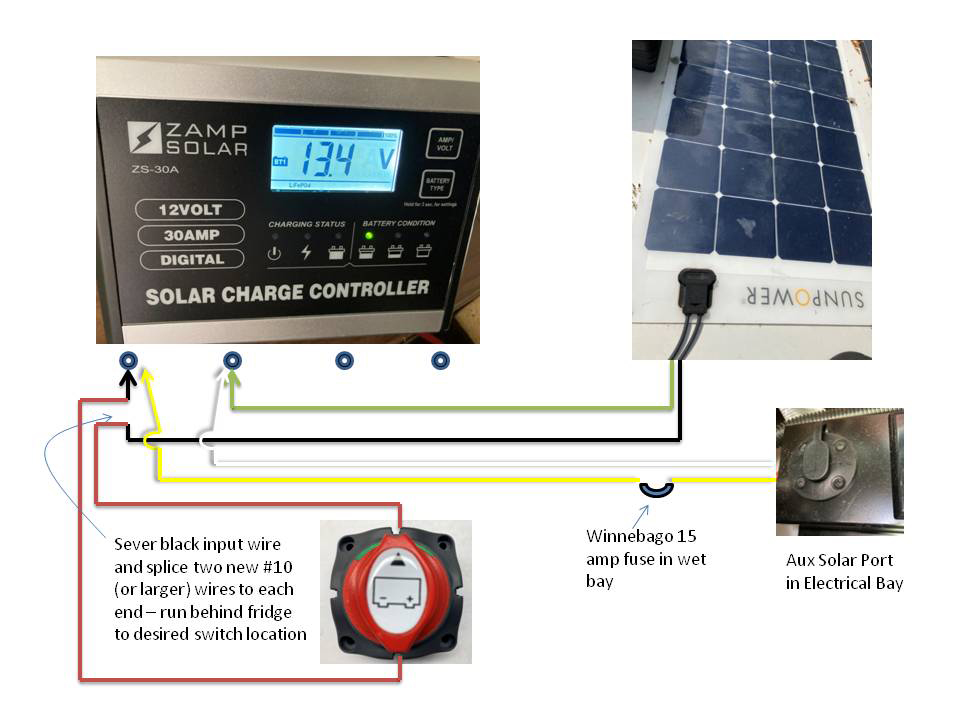
Note: The power OUTPUT of the Zamp controller goes underneath the passenger seat, through a 30 amp circuit breaker, and then directly to the battery bank in the stepwell. If you could pull this circuit breaker, this mod would not be as handy as it is. Unfortunately, you can’t operate the passenger seat circuit breaker, so are left looking for a different way to stop the solar from reaching the batteries. Also in support of this mod, if you could pull the passenger seat circuit breaker - you would not be isolating the roof INPUT to the Zamp controller.
The installation was generally straightforward, but there was some workload involved with fishing the switch wires, and splicing the connections to the solar input wire. Overall, the concept involved finding the solar input wire to the controller, cutting it, splicing two new wires to the severed ends, and then running them in tandem to the remote location of the switch under the bed.
I started by heading up to the roof to unplug the two solar panels from the plug box. (This is a highly recommended step, as depending where you are on the planet and what your current weather is … your panels could be outputting quite a bit of current.) Back down in the coach, I confirmed that there was no solar input to the controller.
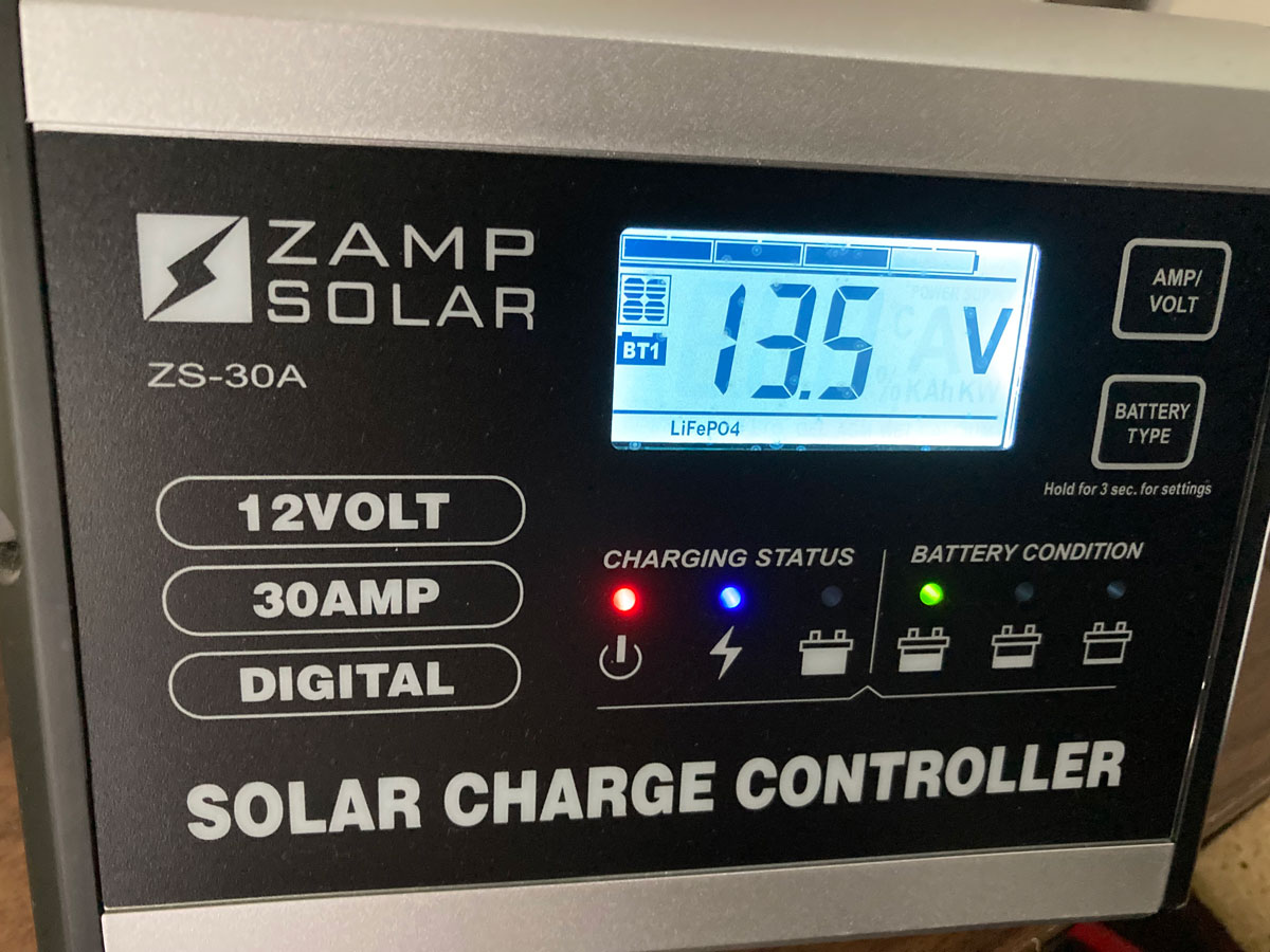
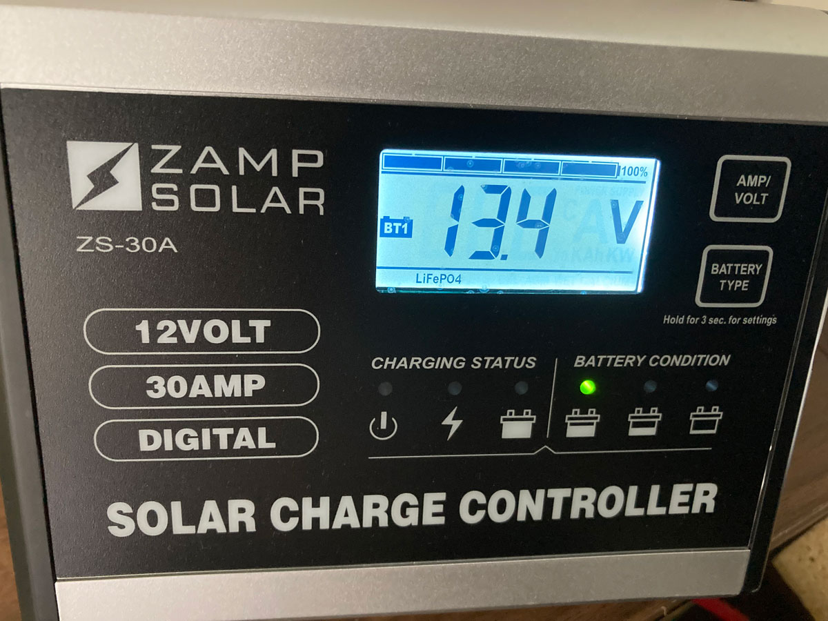
This first photo shows what the monitor will look like with solar available, and the next photo shows the absence of solar input with the solar panel icon in the top left corner of the screen missing and the power and charging LEDs not illuminated:
Finding the solar input wire to the controller was simple: It is the black # 8 wire that hooks up to the extreme left hand terminal (when looking at the front of the controller), or the extreme right hand terminal (when looking at the back of the controller). This solar input wire has been co-located with a yellow # 10 Winnebago power wire, so there is no mistaking. It is the only black and yellow combination on the back of the controller. On this diagram below, it is the extreme left hand line:
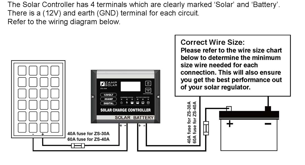
And in this photo, the black # 8 Zamp wire can easily be found at the first terminal location, at the bottom of the groupings:
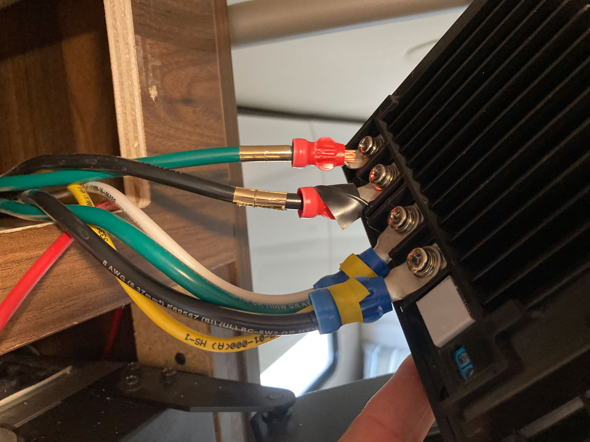
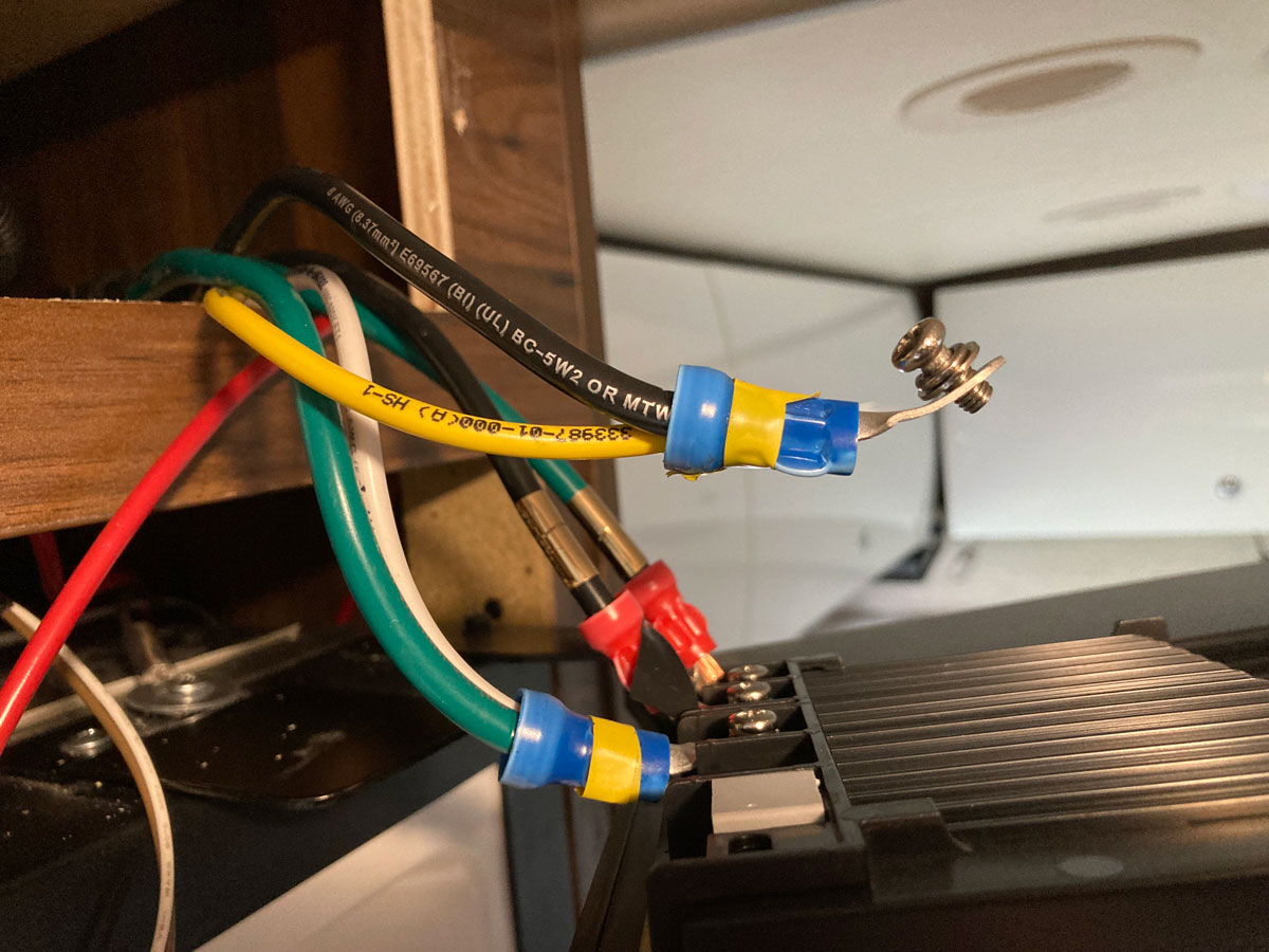
Here is a shot of the terminal ring holding the yellow and black Zamp # 8 solar input wire disconnected from the back of the controller:
The other wires involved were new, and I needed about 15’ of red # 10 wire to run a tandem set from the area of the Zamp controller down to the Truma area. As with previous mods, I removed the control panel from the top of the fridge to provide easy access to the back wall allowing me to drop an electrian’s cable snake down the rear of the fridge and into the Truma area. I found that inserting the cable snake at the right rear of the fridge only required a few tries to make it to the bottom and out to the water heater.
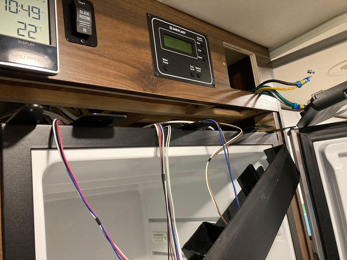
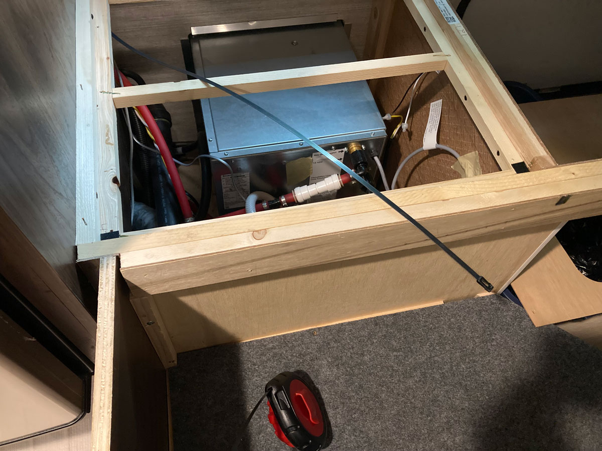
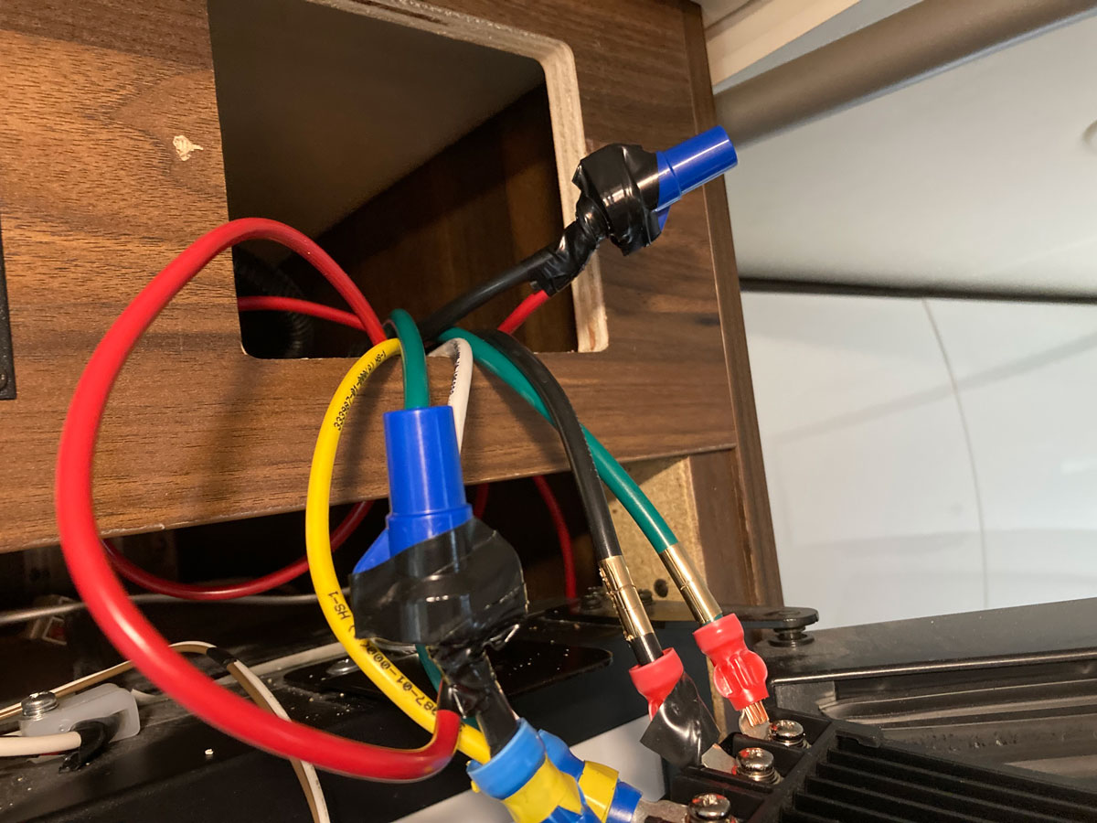
Once I had the two new red wires running from the Truma area to the top of the fridge, I cut the black Zamp # 8 solar input wire and proceeded to splice each red # 10 wire to each end of the severed solar input wire. Due to the size of the wires concerned (a # 8 and a # 10 splice), this was a bit awkward. Ideally I would have liked to use splice connectors that a pro would have been proud of, but I couldn’t find a handy source locally that made this practical. I resorted to using wire nuts, even though I knew that RV professionals frown on this method due to the possibility of the wire nut backing off during potential road vibration. However, I did some research online and was eventually comforted by the technique this video gave me:
Large diameter Stranded Wire Splicing
The wire nuts used in the above video are similar to these:
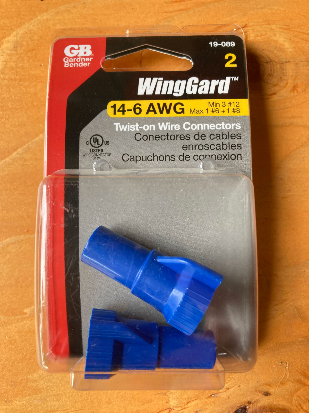
I finished up the splice job by taping the wire nuts to ensure they stayed in place:
The last part of the job was to hook up each red wire, both waiting down under the bed, to the terminals on the disconnect switch - and mount it in a convenient location in the Truma box area. I positioned mine on the fridge wall, left hand side of the Truma box area when looking in, using a couple of wood screws. This location allows you to reach in the hole of the cover panel and operate the switch easily:
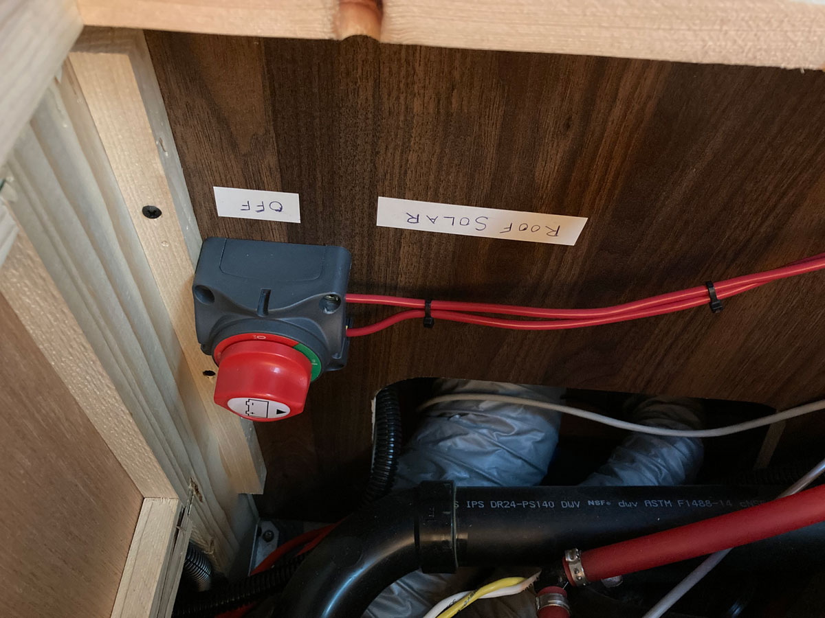
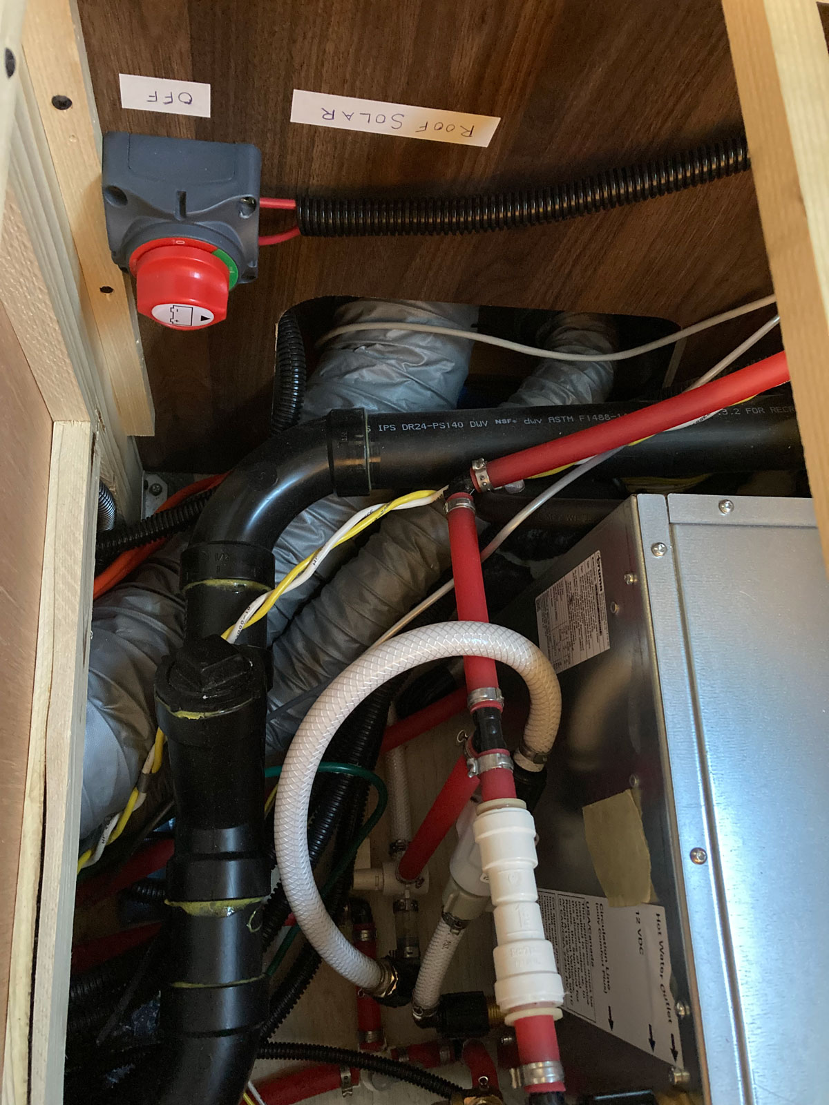
Adding some plastic protective loom to the start of the wire run gave the mod a Winnebago look.
Notes:
1 - I selected the switch to OFF during this installation, so after I climbed back onto the roof to plug in the solar panels I could monitor the Zamp controller’s activation via use of the new switch when back in the coach.
2 - What is that yellow Winnebago power wire that is also connected to the input terminal of the Zamp solar controller? As the diagram above shows, that is the power wire coming from the auxillary solar port in the electrical bay, behind the shore power cord. The 15 amp circuit breaker in line on that yellow # 10 / 30 amp power wire found in the wet bay would be able to accomodate a pretty large portable panel, but you can’t go too big. Don’t forget that the Zamp controller that came with the motorhome is only rated for a maximum of 510 watts, or about 29 amps / 17.5 volts coming from all of the panels you have hooked up. The auxillary solar port in the electrical bay is only rated for 150 watts, so when paired with the 450 watt maximum triple solar port on the roof - you get pretty close to the 510 watts maximum that the Zamp controller can tolerate.
3 – If you have an earlier model View or Navion, it is possible that the installation of a solar disconnect switch might be equally straightforward. The website link below will take you to a View / Navion website that details an installation that appears to have to deal with only the wires shown in the Zamp installation diagram above. And on earlier models there might be some slack available in the cabinet as well!
Another approach - earlier model year View / Navions
Happy Disconnecting!