RV Solar Panel Upgrade | RV Mods
I’ve got mixed feelings on this one – I’m glad to be adding some more solar capability to the View, but I’m disappointed that I have to replace the existing flex panels after only a couple of years of use. People have been reporting that the factory 100 watt SunPower panels have been scorching the thin Filon fibreglass veneer on their View / Navion’s roof, and I’ve noticed a drop in performance of our factory panels over the short period that we have been using them. So, time to fix both those issues while increasing our charging capability to the lithium coach batteries.
Here is what we started with - two SunPower 100 watt flex panels in the factory configuration - in ideal conditions we used to get about 10 amps total out of these panels when they were new:
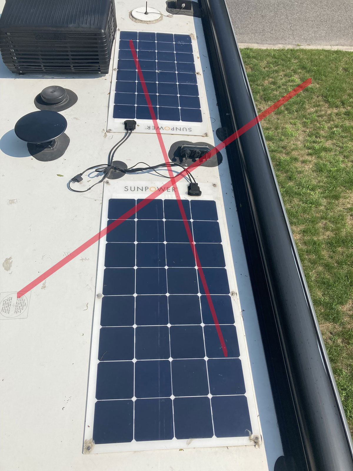
The general concept for this mod involved removing these two flex panels that were screwed (and glued!) onto the roof, and replacing them with four 100 watt rigid panels mounted on a track system – without having to modify the Winnebago solar roof port system or Zamp solar controller.
Installation Considerations:
1 – How to attach the new panels to the roof? No new holes was my number one priority, so choosing a method to accomplish that was given a lot of thought.
2 – Having to go through the process of removing the factory flex panels, screwed and glued to the roof, I eventually thought it would be a good idea to make this next panel installation easily removable with no impact on the fibreglass surface. I wanted a system that would make maintaining or replacing panels on the roof a quick and painless event.
3 – Did I want the added weight four rigid panels and all the installation hardware would bring?
4 – Should I add more than 400 watts? Other folks have been adding quite a bit more solar capability to their Views and Navions …
Here is what I came up with:
After looking at numerous panel installations on both YouTube and the Winnebago owner’s forum, I settled on the 3M 4950 VHB double sided tape option for securing them to the roof. AM Solar out of Springfield, Oregon, has pioneered the use of VHB tape for solar panel retention and offers this as a vote of confidence:
“Fiberglass roofs – We have been using a type of 3M double-sided tape on our mounts since the mid 1990’s, and we have never lost a panel. As long as the tape is properly installed on a clean surface at the correct temperature, it will hold. As an added level of protection, we use a layer of Dicor self-leveling sealant around the entire perimeter of the mount, and cover the screw holes/heads as well. The sealant protects the tape and any potential roof penetrations from water intrusion and decay. Some customers use the screws for an added layer of protection on fiberglass roofs, but we haven’t found that to be necessary.”
“Rubber Roofs – Along with the 3M double-sided tape, we also include stainless steel ¾” sheet metal screws in the Rocker Foot Mount Set. While the 3M tape will hold to your rubber roof, your rubber roof may not stay attached to the plywood it is bonded to. The sheet metal screws will penetrate through the rubber, into the plywood, to keep your rubber roof from separating while the wind force of highway speed driving pulls at your panels. Again, we bury the entire mounting feet with Dicor self-leveling sealant for weather resistance.”
Ok, so a well respected national leader in solar panel installation has never lost a panel when using VHB tape… how much tape do they use? They don’t use that much, actually. If you go to their site and shop for replacement feet, you will see that they only use a 1” wide strip 2.5” long on each foot. 2.5 square inches for each foot gives you ten square inches of adhesion footprint total. The 3M 4950 VHB tape is rated for 140 lbs of tensile pull strength per square inch, so that works out to 1400 lbs of vertical pull force on a panel. Seems like quite a bit of safety margin…
Grandpa Ron added a new panel using the AM Solar method – his installation video can be found here:
Grandpa Ron sounds pretty confident in the use of the tape; it looks like he has industry experience that has formed that opinion. Between Grandpa Ron, AM Solar, and a bazillion other RVers out there who have installed panels using VHB 4950 tape, the tape / no holes method was looking like a winner.
Ok, I made the decision to use the VHB tape and started into the same type of installation that Grandpa Ron had done – but elected to use six feet, instead of just four. (This would have given me a 50% increase in factor of safety compared to the AM Solar method) I came very close to getting up on the roof and starting into it, but due to the onset of a cool fall season, I ran out of consistent ambient temperatures that fell within the VHB tape installation parameters. I had everything ready to go, but was forced to drop tools and sit on the installation until the following spring and the arrival of warmer temperatures.
It turns out this was not a bad turn of events, for I started questioning the advisability of attaching panels to the roof with no easy way of removing them. That is when I noticed Brian of “RV with Tito” had come up with an installation system that used Utility T Track, and his project looked pretty good - as usual:
I have always envied those that have roof racks that can be used as the supports for a solar install, so the idea of using Utility T Track looked like the next best thing. In addition to being able to remove a malfunctioning panel quickly and easily, the added adhesion footprint that the T Track gave was the clincher – If AM Solar was happy with ten square inches of VHB footprint for the large panels they install, how about 9 times more adhesion than that for my small panels?
So, with a long winter ahead to change direction and plan an installation using Utility T Track, here is what my supplies list ended up being, with associated links:
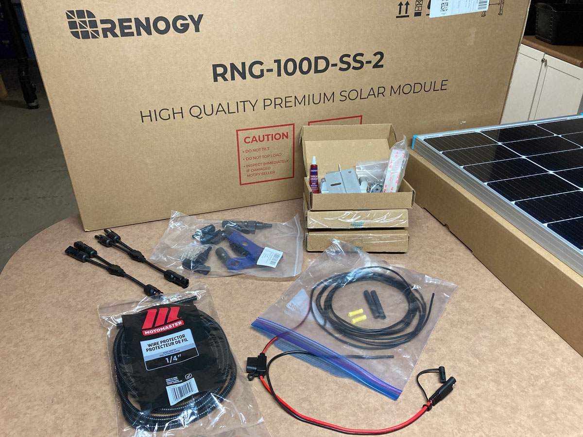
Renogy 100w rigid solar panels
Here is the data sheet from the back of one of the panels - based on this, I was looking forward to a solid 20 amps of charging in good conditions:
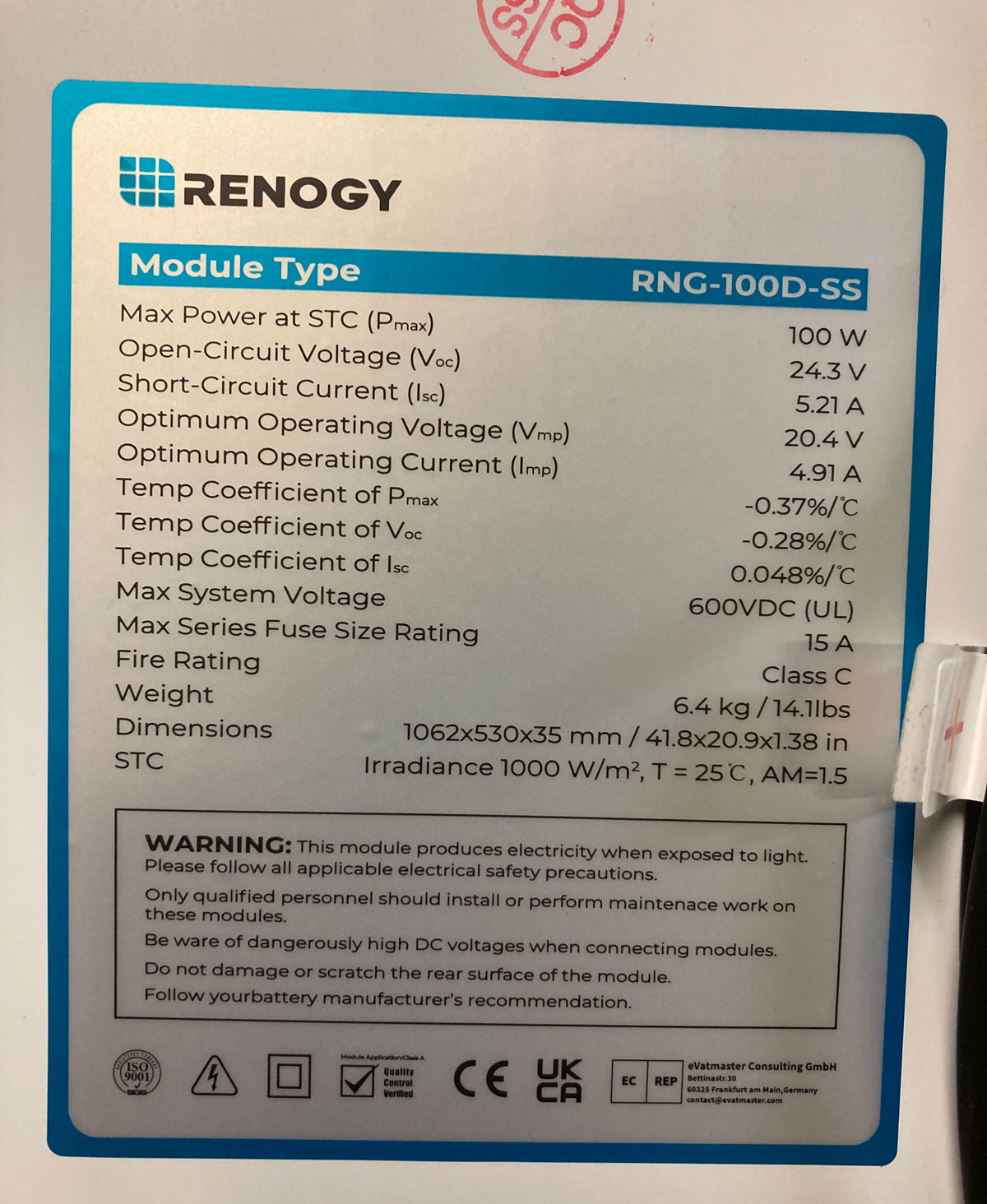
Do you need a fuse on the direct output of a solar panel? Well, good question. Our View has a 15 amp fuse on each of the current panels on the roof – I assume that Winnebago and Zamp decided this was necessary to protect the input to the controller. (The battery charge wiring output from the controller is protected by the 30 amp solar circuit breaker under the passenger seat.) Using the Winnebago and Zamp guidance, a 20 amp fuse to protect the combination of the output of the additional two panels made sense.
Renogy Z brackets for panel mounting
I chose the Renogy feet to keep things simple; as they were designed for their panels.
All of the installations online that I researched had used ¾” Utility T Track, but I chose 1 ¼” T Track to allow the use of a full width strip of 1” VHB tape. ¾” VHB tape is not as easy to find, and I liked the idea of more adhesion footprint.
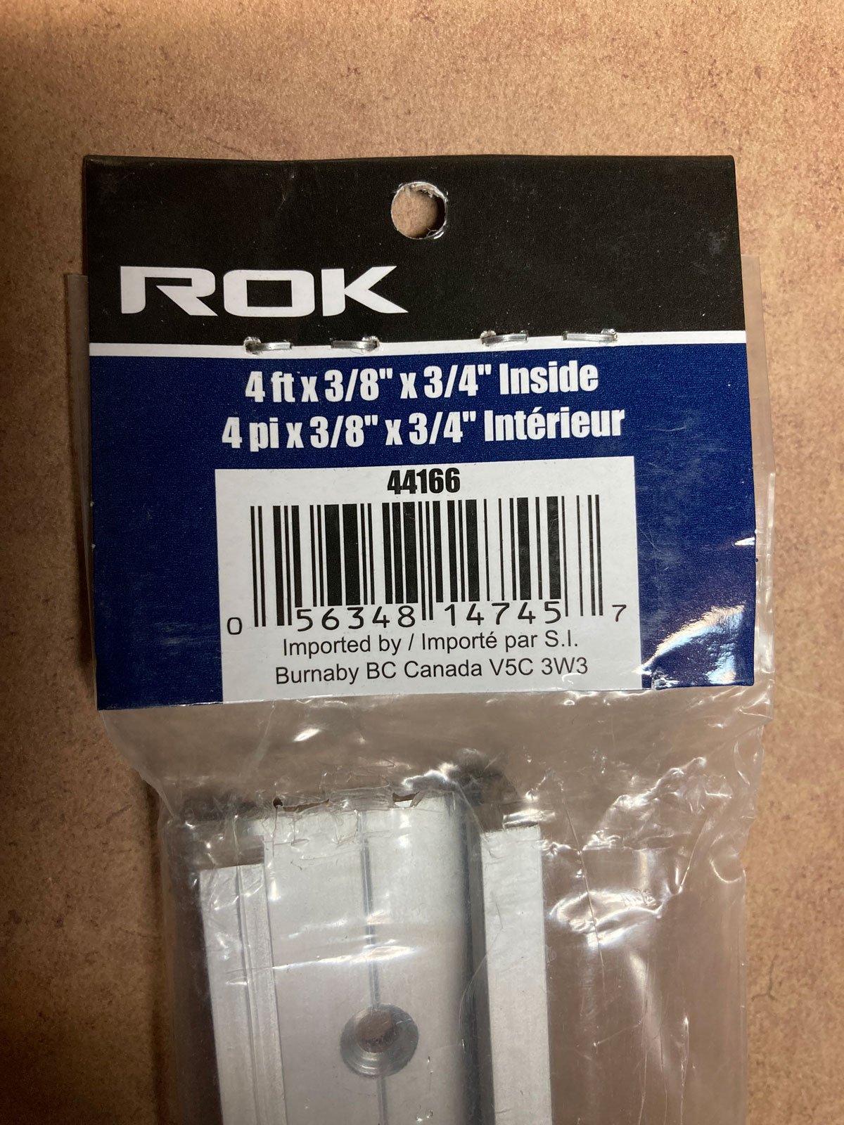
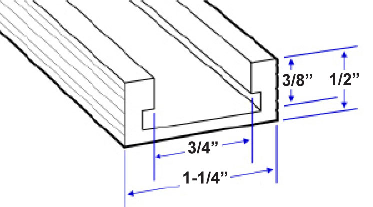
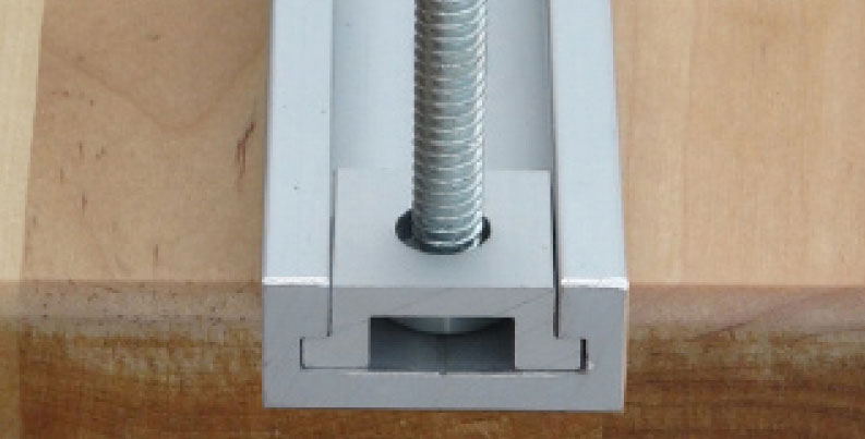
The T Track I chose really lends itself to needing some sort of bolt anchor, due to the width of the track. A ¾” track would allow just a bolt insert, but the 1 ¼” wide track is too wide for that practically. Here is a photo of the mounts I purchased, being used in a carpentry application:
¼” – 20 ½” bolts, nuts, lock washers, all stainless steel – These bolts are more heavy-duty than the bolts that attach the feet to the panels, so I considered going a bit smaller to match those bolts … but in the end I went with these ¼” – 20 bolts, as they are pretty easy to find.
#12 AWG wire, butt splice connectors, shrink wrap tubes, and gutter and siding sealant.
How much extra did this all weigh? The panels and feet are 15 lbs each, the Utility T Tracks per panel add another 3 lbs, and the miscellaneous wiring, connectors, and sealant was probably about 3 lbs total. I took credit for the weight saving of removing the flex panels; about 8 lbs. That all comes in around 67 lbs, but when taking credit for the rear stabilizers that I removed, the net additional weight totals about 27 lbs. I rationalized this as a good deal for a theoretical 400 watts of solar capacity that actually had a good chance of working for awhile.
Was 400 watts going to be enough? I saw that some View owners were coming up with 600 watts for their retrofits – but I did notice one significant drawback to this concept – available real estate on the roof to walk around and maintain things. At some point I’ll have all of that roof sealant to replace, and I felt I should plan for a comfortable work environment to do that and other roof maintenance jobs without having to remove the panels. Also, our Zamp solar controller is only rated for 510 watts total, and they recommend only a maximum of 450 watts on the roof. We have never used the solar inlet located in the electrical bay (that one is rated for 150 amps), but even still – I didn’t want to get involved in adding a different solar controller with more capacity. No, 400 watts capability / 20 amps of charging was about all I felt we needed.
The Installation
1 – With my change of plans to allow the panels to be removed easily from a T Track concept, I moved the Renogy feet from the side of the panel to the ends. There are existing holes in the panel frame to allow for configuring the feet on the ends.
IMPORTANT – Using the Renogy feet on the ends as I did, with the existing panel frame holes, does not allow for the panels to revolve around the attachment bolts - in case a roof is not flat. For the View / Navion, this is not a problem – as the roof is flat enough that the panels will sit flush with the T Track. But, if you are using this installation information to get ideas for your RV, and your roof is angled enough that the rigid attachment of the feet won’t allow the panel to sit flush on the tracks, this will cause a problem. In this case you will have to drill holes in the face of the panel frame and use angle brackets and fasteners that allow the feet to pivot and lay flush with the track. Not a big deal to do, but really important. You don’t want to bolt down your panels with a residual panel pull force on the track and VHB tape.
But, again, for the View / Navion – all is good. The roof is flat enough that this is not a problem.
I needed to drill a hole in the centre of each foot to accept a T Track bolt. I landmarked the location of the hole using the letters stamped on the foot – I chose to use the end of the centre line of the E to ensure repeatability. I drilled an oversize hole for use with the ¼” – 20 bolt, in order to allow for some lateral play that might be needed due to inaccuracies in the Renogy panel holes, or my drilling locations. You just never know…
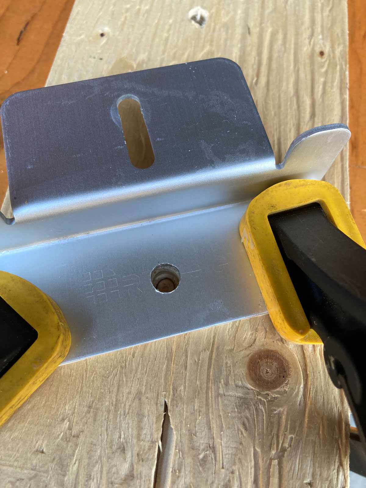
I attached the Renogy feet to the ends of the panels, landmarking them for repeatability using a spare mounting hole as a reference. Getting all of the feet in the same location, with the hole in the same location on each foot, was key to being able to mount the panels on the T Tracks after all of the tracks had been laid. There are no second chances for positioning the track!
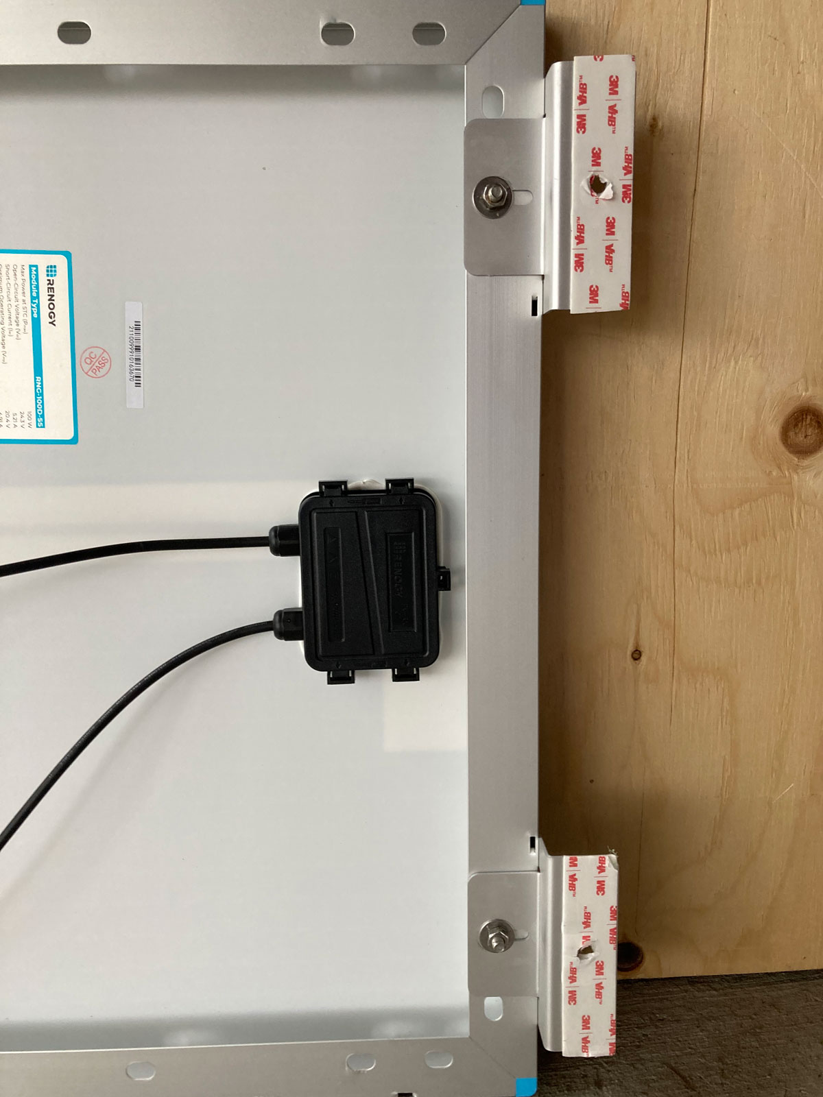
(You can see the old VHB tape on the bottom of the feet, now redundant since I changed the method of mounting the panels. The VHB tape on the feet was not used.)
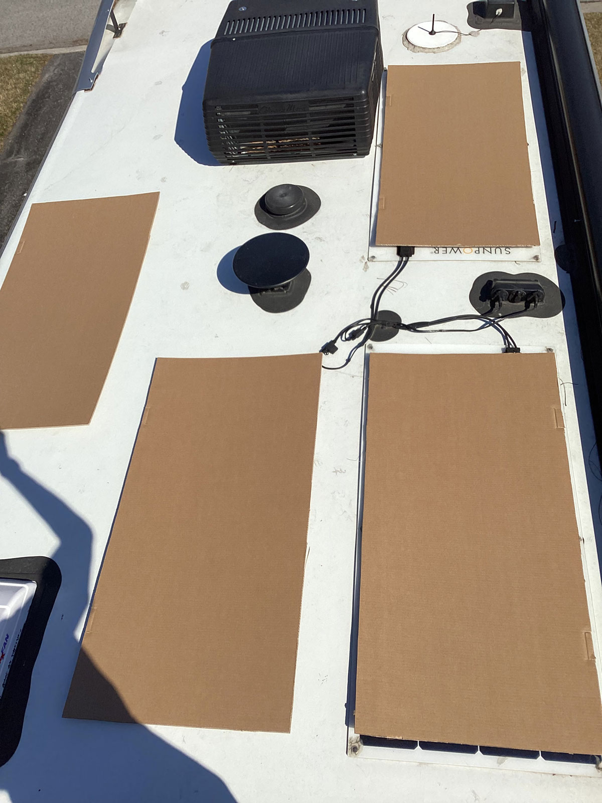
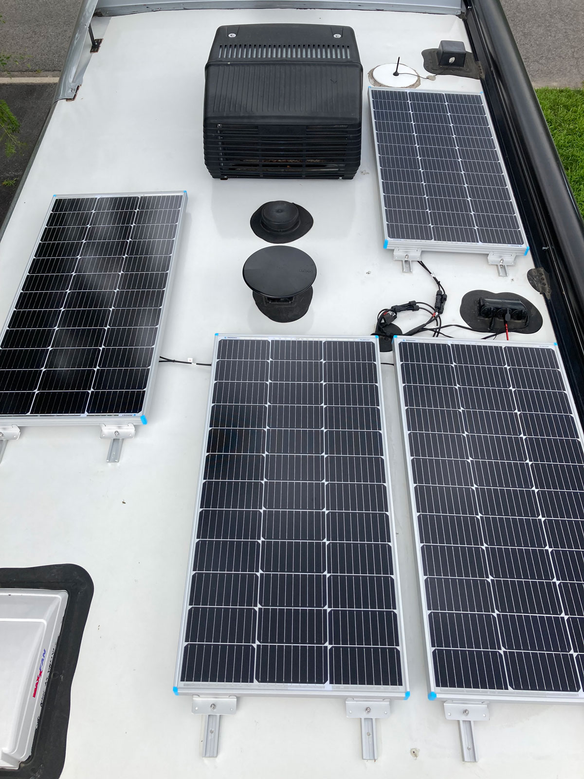
2 - As I mentioned earlier, I wanted to leave some room to be able to walk around on the roof. In addition, I wanted to minimize a shadow from the airconditioner. The orientation and placement of the panels seemed pretty intuitive, but I cut up the boxes that the panels came in and used them to mock up the ideal locations for the panels … just to be sure. Getting around the airconditioner to work on it and being able to access the front of the coach was important, so I took care to be able to do that without resorting to gymnastics. Ideally I would have liked to position all of the panels ahead of the rear axle, but that was not possible if I wanted to leave room to walk around the roof. The 100 watt Renogy panels are not huge, so here is what I quickly ended up with:
3 - With a plan as to where I wanted to put the new panels, getting the old panels off was the next step. This turned out to be much more difficult than I thought it would be. The six screws per panel were very loose and not really doing much of anything, but the panels were also glued down! My plans were to get the panels off the roof without any panel damage, but breaking the adhesive bond meant that I heard some cracking as I tried to pry off the SunPower flex panels. I’d recommend doing this job while the sun is not shining, as those things get hot! After I got the panels off, I did check the output voltage and found that both were still in the 18 volts range so perhaps I can still pass them to a friend with a clear conscience.
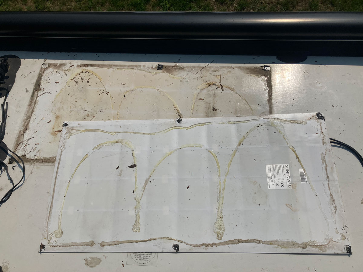
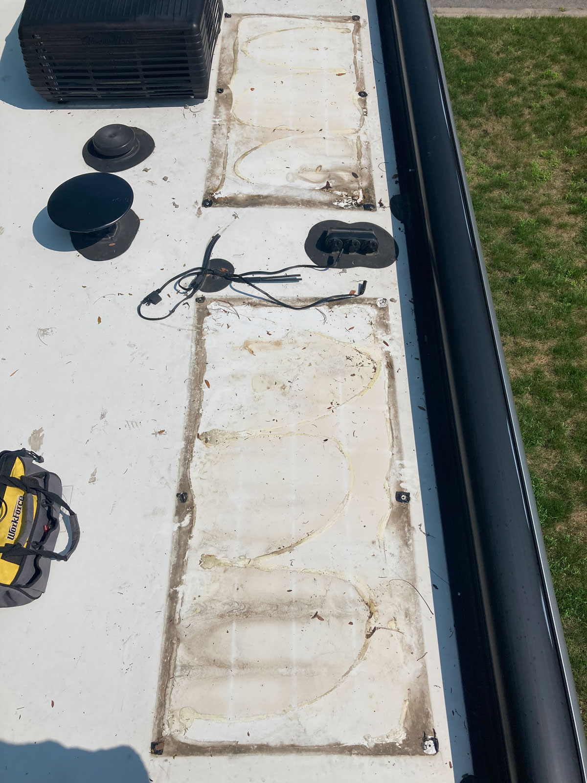
4 – After I got the old panels off of the roof, the scorching that others had reported was there – but not as bad as I had feared. I guess the temperature of our panels did not reach the values that can be reached by coaches that live in southern states. There was some micro cracking in the areas of the light scorching, but I didn’t see anything that looked like a structural problem.
Here is a closeup of the scorching that was on a small area of roof - with the flex panels lying flat on the roof, all of that heat would be transferred to the thin Filon fibreglass layer. For the most part, when laying the T Track I was able to miss these bad areas:

Here are a couple of photos of what I was left with after the panels were removed:
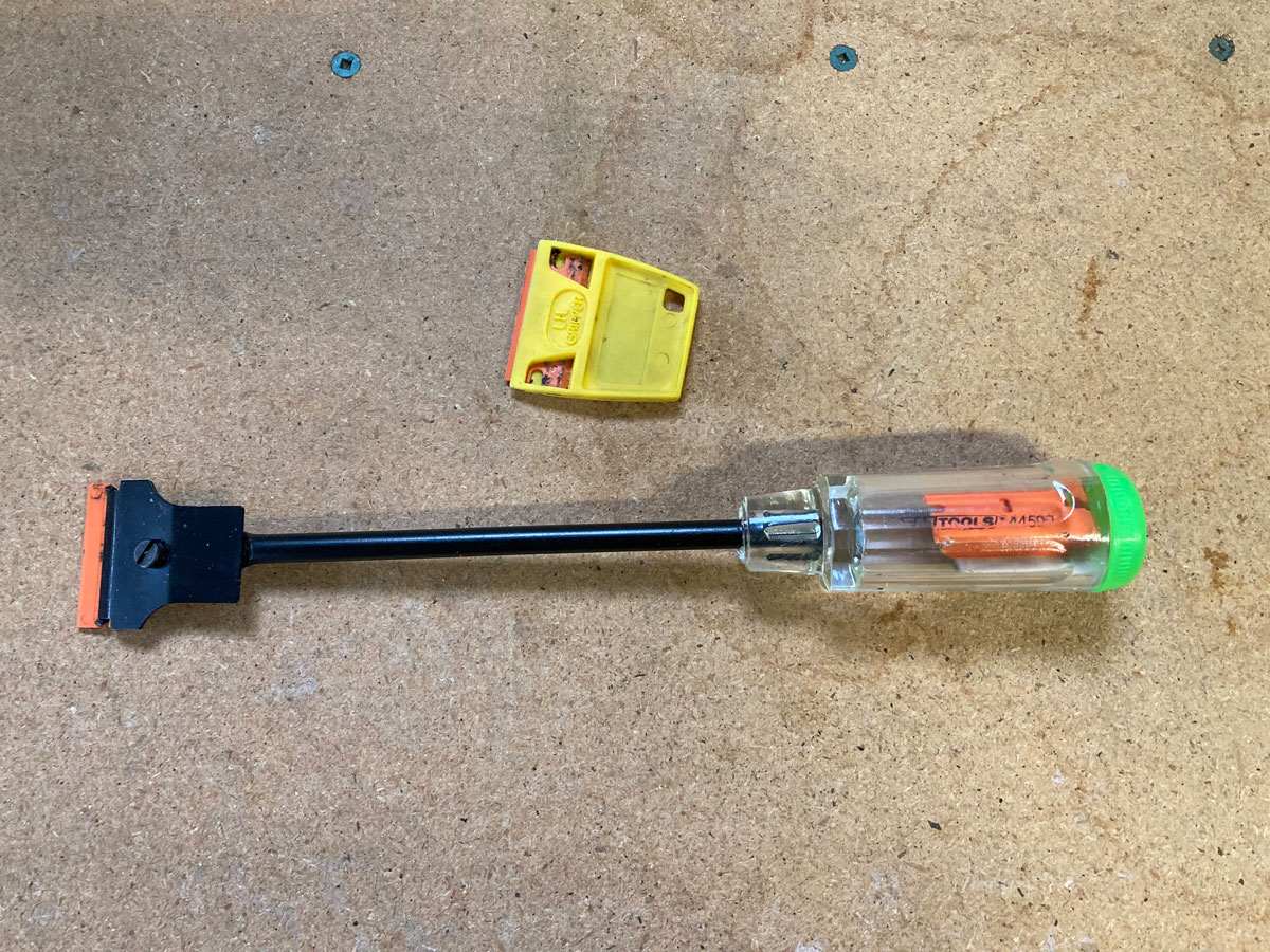
Getting the glue lines off the roof was the next challenge, and for that job I used a plastic razor blade scrapper and some paint thinner / mineral spirits. The scraper I used during my rear view camera project did not lend itself very well to putting a lot of force into the work, so I bought an extended handle razor blade scraper that allowed one to get serious about the job. In this next photo, the top scraper is the one that came with the plastic razor blades, and the bottom scrapper is the one I bought to make the job much, much easier:
I found the adhesive residue came off easier after spraying on some paint thinner, and it also removed the sealant residue around the screw holes very well.
I sealed the SunPower screw holes with gutter and siding sealant. I contemplated putting the screws back in the holes as well, but for simplicity I settled on just the sealant. The sealant I used at various times during this project was the same product I used during my rear view camera replacement. Lichtsinn RV use this product to seal the roof radius after roof maintenance, as it has a superior bond with fibreglass. If it is good enough at keeping the roof on, I figured it would be fine for this job. The sealant is Stone Mason Gutter and Siding Sealant, and is available both north and south of the border:
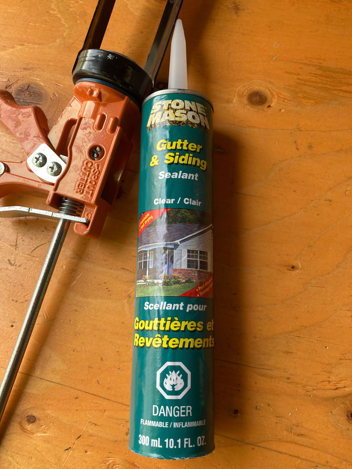
I quickly zeroed in on the fact that the only part of the roof that needed to be super squeaky clean was a 1” by 48” strip where the T Track was going to sit. During the trial panel placement phase, I marked where the T Track was going to end up using painter’s tape, and this made it much easier to concentrate on getting only the important part of the roof pristine. I used the scrapper and paint thinner first, followed by a 50 / 50 blend of rubbing alcohol and water. The next day, when I actually installed the T Track, I went over the area again quickly with a fibreglass cleaner, the paint thinner, and then the rubbing alcohol / water blend. That combination seemed to work well.
5 – The attachment of the 4950 VHB tape was straightforward. Here is a link to 3M’s installation instructions for the VHB tape. Lots of good stuff here:
3M VHB Tape Installation Instructions
This is an excerpt from the 3M 4950 VHB tape specification sheet that I found helpful:

I elected to scuff up the base of the T Track with some 1200 grit sandpaper, and then cleaned off the area with the alcohol / water blend. I positioned the tape in the centre of the track, and then used a roller to apply pressure as described by 3M. When installing the track onto the roof, I walked on the tracks to apply the required pressure.
6 – The placement of the T Track had to be right, the first time, so I elected to cut some spacer boards to ensure an accurate installation. The awning side T Track was to be located 4 ½” from the awning base plate, so I cut a 4 ½” spacer board to allow me to drop the track accurately. I used this 4 1/2” spacer board for both of the awning side panel’s first laid track:
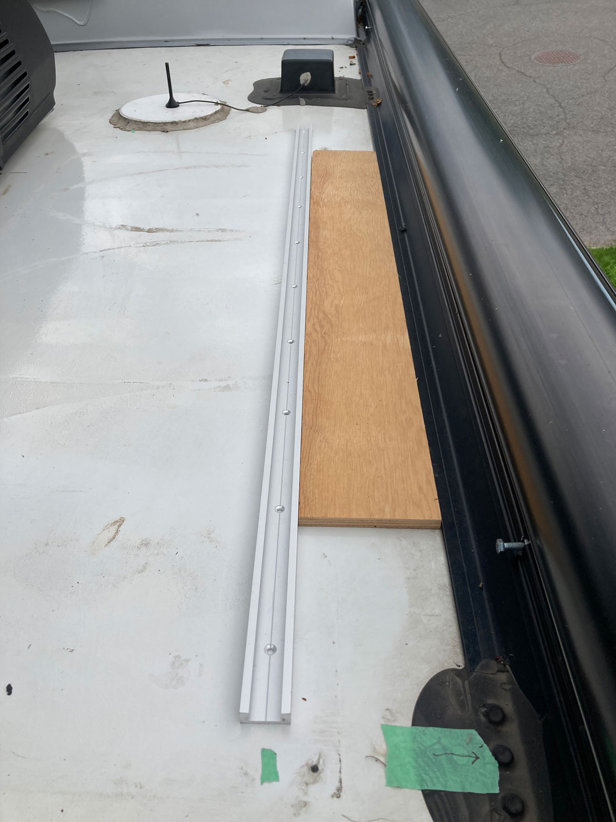
The second track laid, on all panels, had to be perfect - so again I used a spacer board to get it right. I cut this spacer board 12 and 5/8” wide, to match up exactly with the width of the tracks required for the panel feet to fit on the T Track bolts. With the spacer board butted up against the first laid T Track, it was easy to drop in the second track accurately.
For the centreline panel, or third panel, I chose a 7 ½” T Track separation from its awning side neighbour to align these side-by-side panels. I cut a 7 ½” spacer board to landmark the first track placement, and then used the 12 5/8” spacer board for the second track, as before.
All of these spacer boards were worth the time it took to cut them, as it made the track install pretty darn easy. Here is an example shot of how all the spacer boards were used:
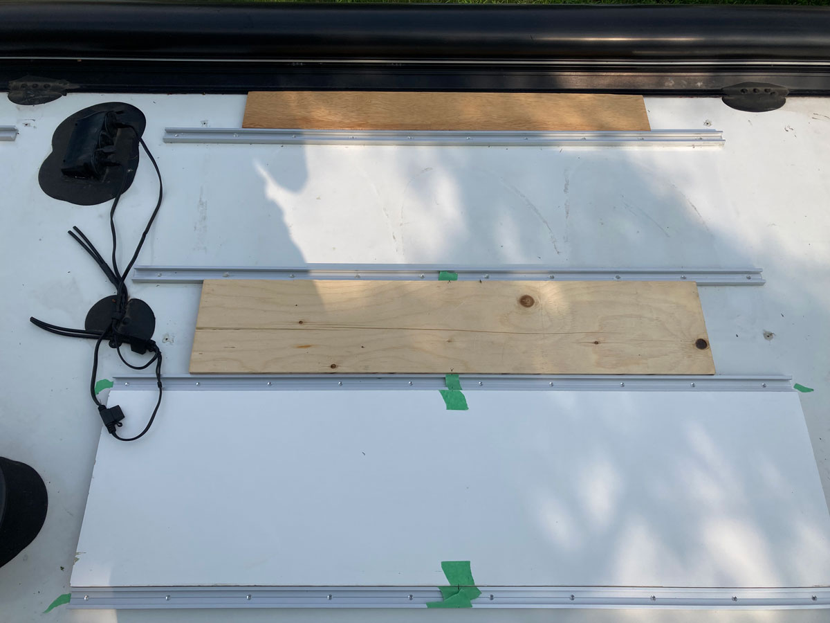
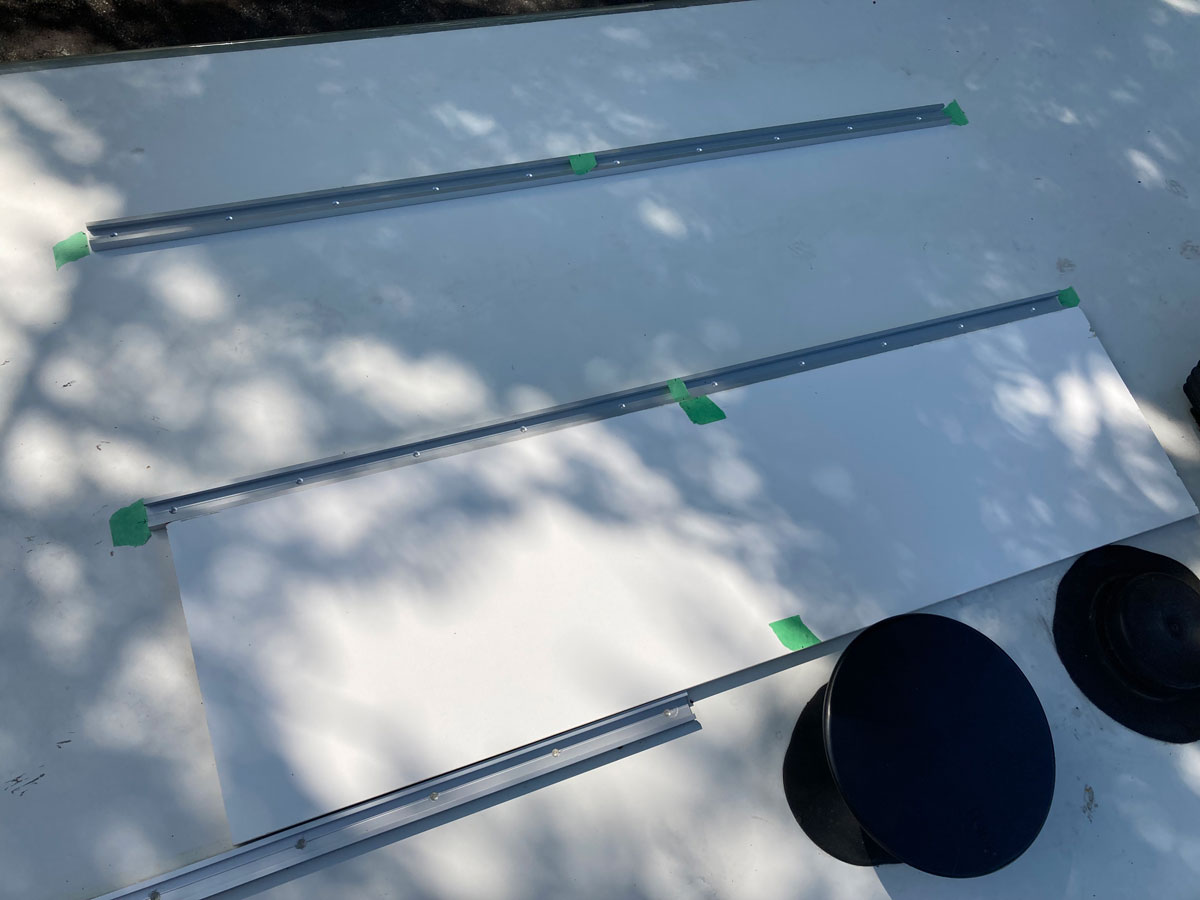
For the slideout side panel, I decided to use the 12 5/8” spacer board aligned along the closest centreline T Track to position the last panel’s first track. Then, I again used the 12 5/8” spacer board to position the last track. (I considered landmarking the track placement for this panel using the paint line along the edge of the roof, but after looking at that for a bit I noticed that the paint line was not straight …)
Here is how I laid the last pair of tracks - to keep them parallel with the other six tracks:
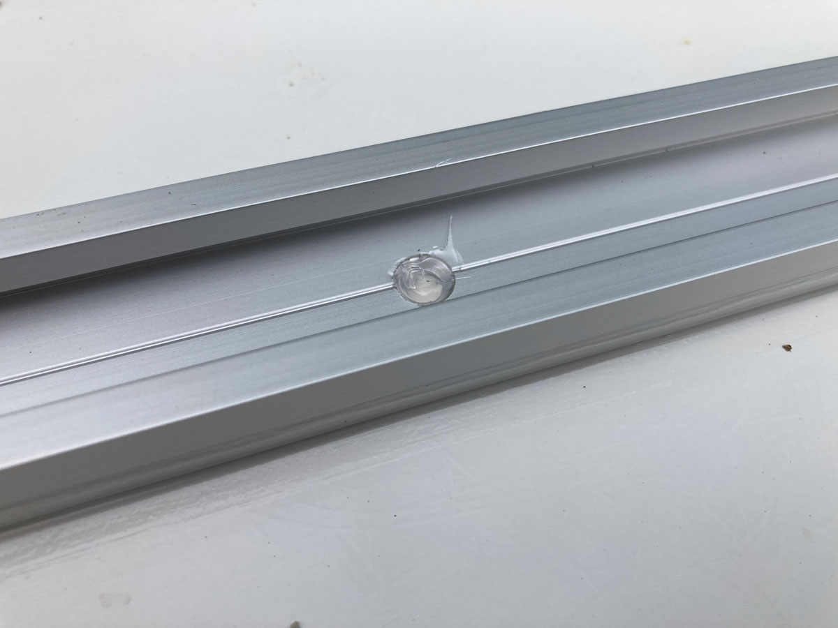
7- I finished up the track installs by running a bead of the siding and gutter sealant along all sides and ends of the tracks. In addition to the sides of the T Track, I also filled in each screw hole on the centreline of the track. (All I was trying to do here with the sealant was to keep the elements and sun off of the VHB tape, so any product that adheres to fibreglass and aluminum would have been acceptable. I elected not to use Dicor self-leveling sealant, as that product gets dirty pretty quickly.) Also, this Stone Mason Gutter and Siding sealant is super strong so I felt good about some extra adhesive in the small groove bordering the VHB tape at the base of the T Track.
Here is how the four pairs of T Track looked once all installed, sealed, and the roof cleaned up:
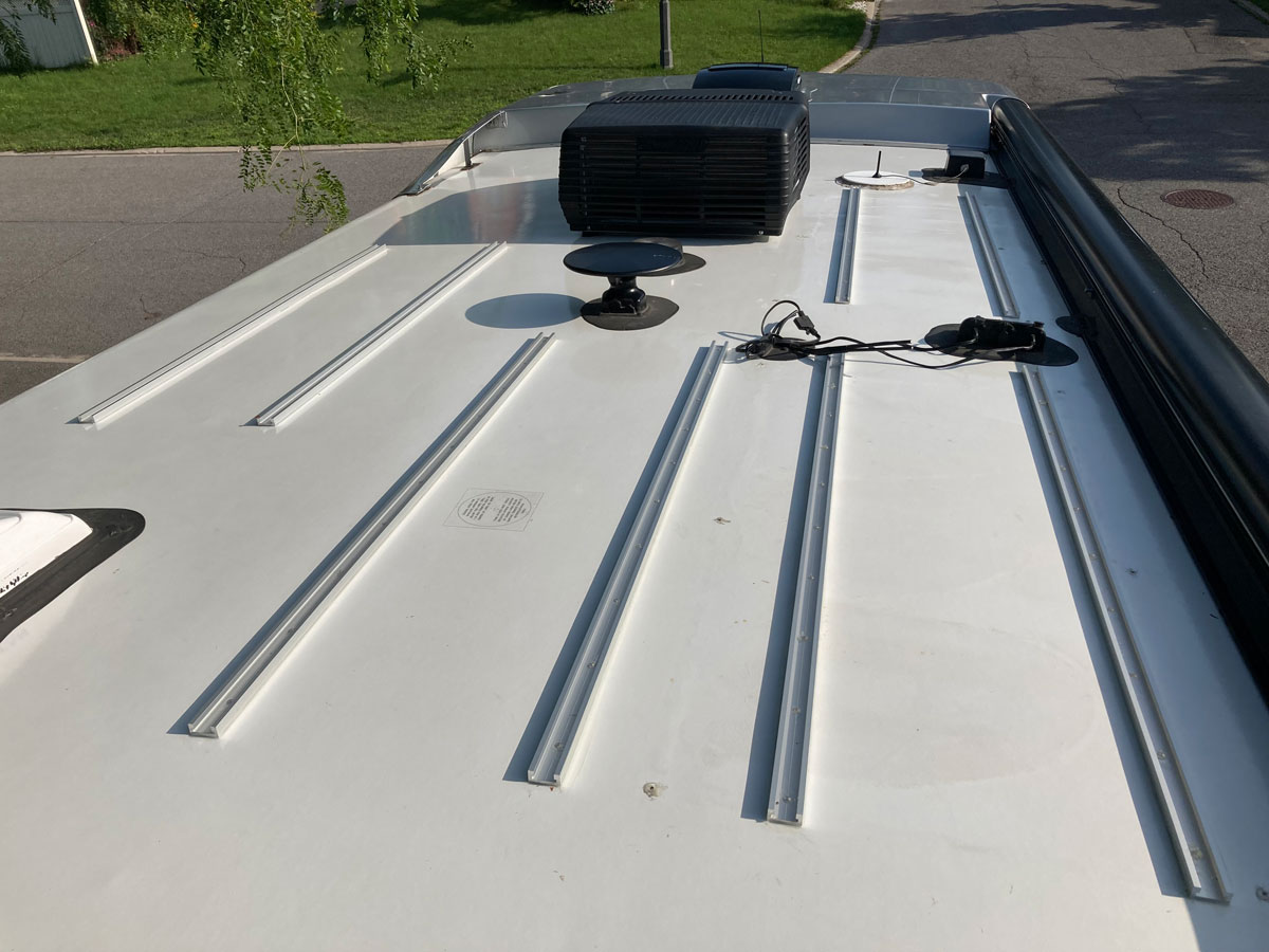
8 – With the tracks installed, all the hard work was done and I moved onto the fun part. The panels all dropped onto the bolts nicely from the T Track anchors, and after sliding them on the track to a position that made sense, I locked them down.
9 – The wiring was straightforward, and the three new pairs of MC4 connectors were easy to work with. (The male connector body uses the long conductor sleeve, and the female connector body uses the short conductor sleeve.)
Here is a link to a short video on the essentials of wiring with MC4 connectors:
Solar wiring with MC4 connectors
I had to buy an MC4 crimping tool – these tools are quite expensive up here in Canada if you buy one from a solar specialty shop, but I found the one that all of the videos use - for a fraction of the cost. Here is the Amazon link:
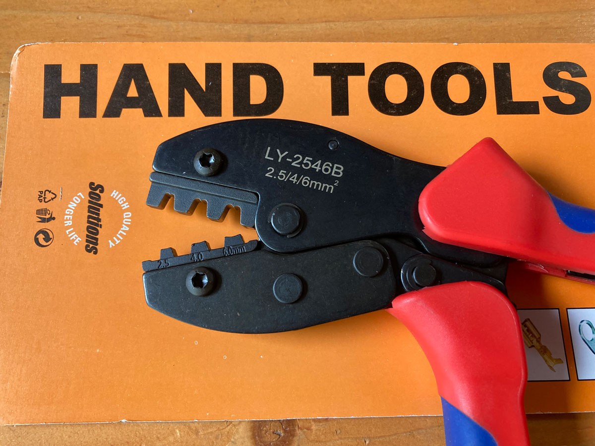
(When holding the crimping tool with the model number reading up, the conductor sleeve tabs point up so they get folded over. I used the crimp jaws closest to my hand.)
Here is a diagram of how I wired up the new panels:
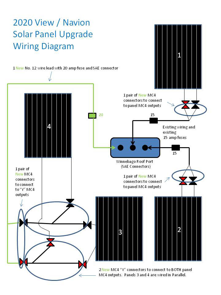
In order to keep things simple for the panels that were replacing the old SunPower flex panels, I re-used the Winnebago SAE connector wires by severing the wires up close to the old panels, and then added appropriate MC4 connectors to connect to these new panels that were located in the same location as the old. I didn’t have any previous experience with these MC4 connectors, and was not sure how they would hold up sitting in spring snow meltwater, so I elected to keep them from sitting on the roof.
NOTE: The positive pole of the SAE connector is on top as it is inserted into the Zamp roof port receptacle. Also, our in-coach “Solar Off Switch” came in handy during this wiring phase, as I didn’t have to cover up the panels to prevent worries about them pushing current during the MC4 connector mating, or when goofing around with the Zamp rooftop port.
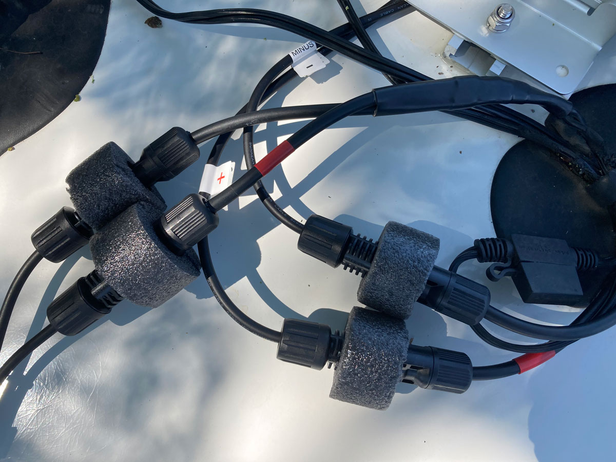
For the two “new” additional panels (centreline #3 and slideout side #4), I needed to use the MC4 Y connector leads and the new SAE connector wire with the 20 amp fuse. Each positive MC4 connector from these two panels were grouped on one Y connector, and each negative MC4 connector was grouped on the other Y connector. (Parallel wiring for these two panels…)
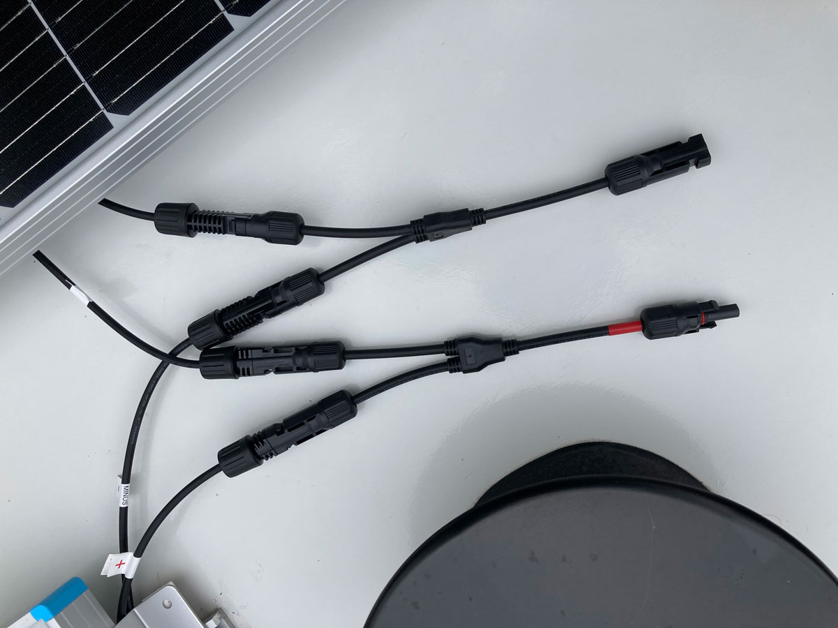
Both of these Y connectors were hooked up to some # 12 AWG cable via two new MC4 connectors, and the #12 AWG cable was spliced to the SAE connector wire using butt splices and shrink wrap:
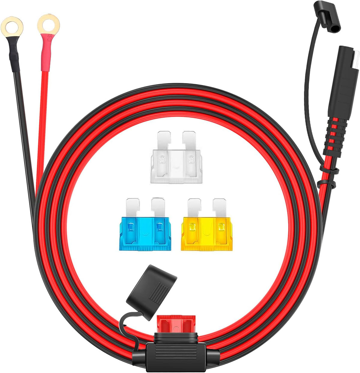
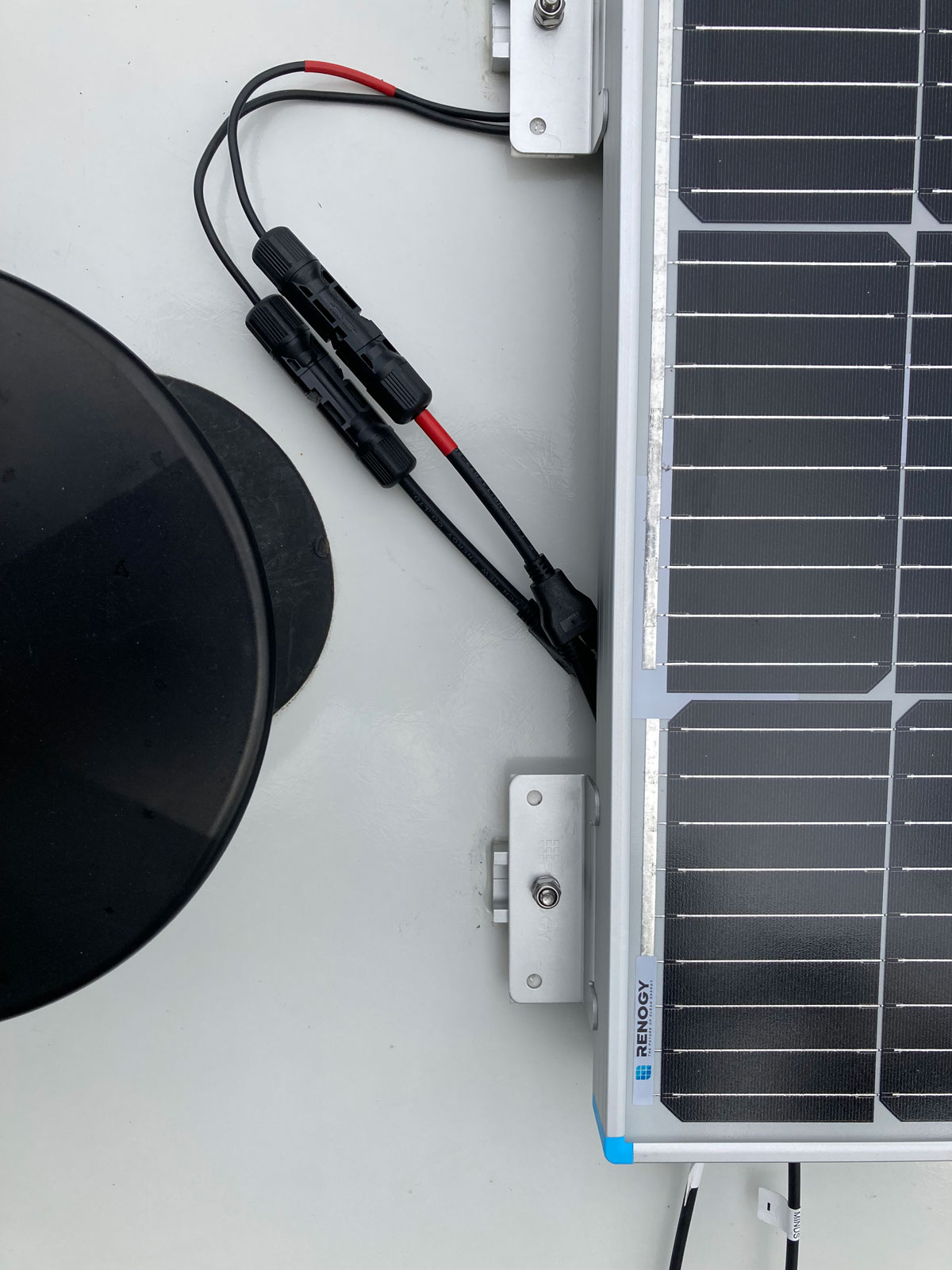
The new SAE connector wire was then plugged into the vacant centre port on the roof top Zamp port box. (This box is rated for 450 watts, so we have a comfortable margin with our newly installed 400 watts.)
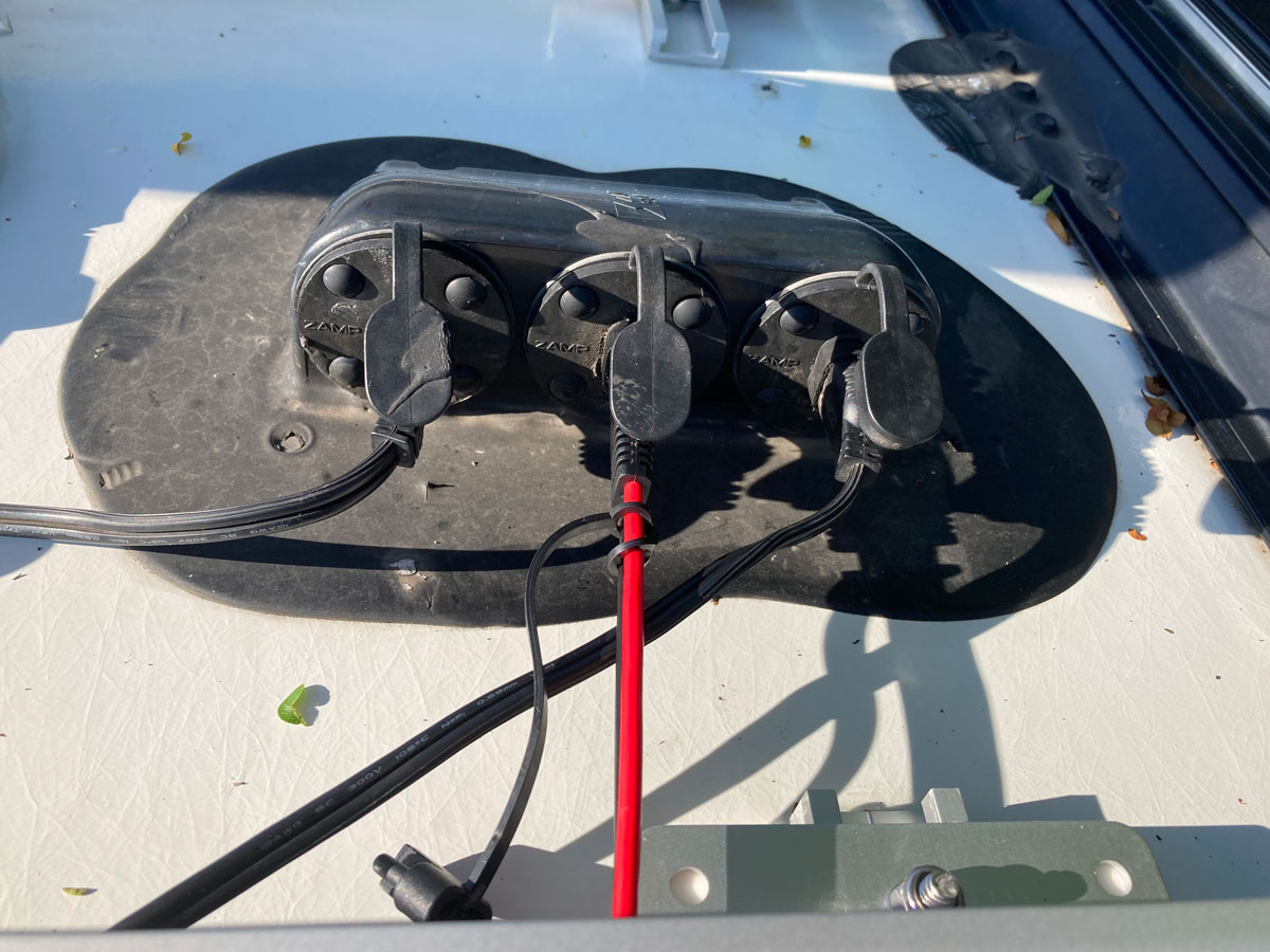
I arranged the rooftop wiring to protect the connectors from the elements, as best I could, to finish the project. Here is how everything ended up looking:
Based on the panel’s data sheet, I had expected to get a little over 20 amps of charging in good conditions - but was pleasantly surprised to see much more than that at times:
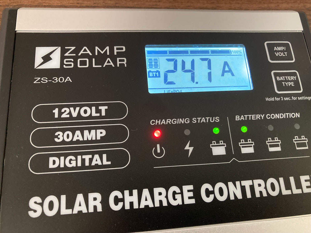
Working better than we hoped it would.