RV Battery Monitor | RV Mods
When we made the decision to install lithium batteries we knew that we’d need a battery monitor of some sort. All reports are true – you can’t tell the state of your lithium batteries just by looking at the voltage. With a voltage drop under load, combined with the very consistent voltage while resting, you are just guessing what you have left in the tank. After looking at all of the videos on YouTube, we opted for the Victron BMV 712 – mainly due to all of the good reviews and ease of installation. Again, Grandpa Ron’s channel was very helpful during this selection. Have a look at his installation here:
After having a close look at the battery box, and noting that things are pretty tight in there, I too elected to install the electronic shunt on the forward riser of the step. (The shunt is essentially a break in the ground wire attaching to the battery bank that temporarily diverts the current through an electronic meter. This electronic meter measures the current, leaving via a discharge or entering via a charge cycle, and keeps track of the numbers. The Victron continually does the arithmetic and comes up with a continuous reading of your battery’s current state of charge.) The install is not tricky; looking back I’d say the workload is getting the ground wires off the batteries and positioning them to be able to attach them to the input of the Victron shunt.
If you are swapping out your batteries to lithium or AGM, then this install fits nicely into all of the cable swaps that occur during the battery changeout. The only caution I’d give is in regard to the ground wires – make sure you get ALL of the ground wires off of the batteries and on to the shunt in order to allow the Victron to truly measure ALL of the current leaving and entering your battery bank. There is no danger in leaving a stray ground wire attached to a negative post, but your Victron will not give you an accurate reading of battery state of charge, or correctly show you charge and discharge data.
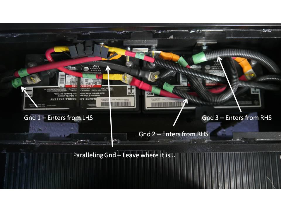
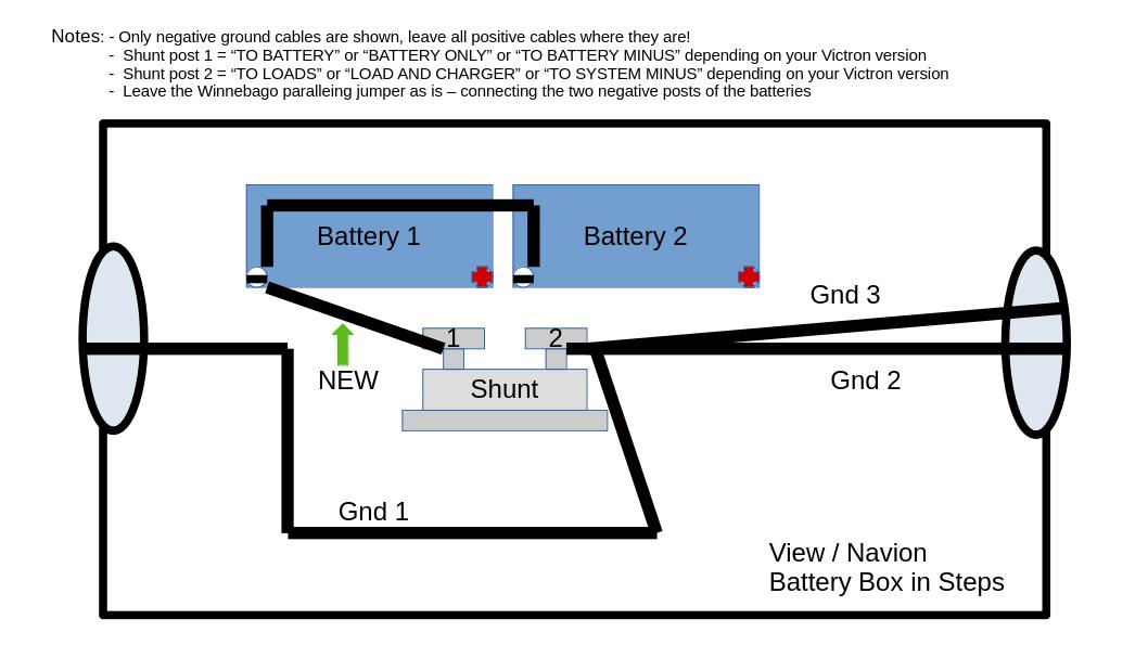
Have a look at the next photo - in the View / Navion there are a total of four existing ground wires that have to be taken into account. One of the existing Winnebago grounding cables comes out of the left hand hole in the battery box (Gnd 1) , the second and third existing grounding cables come from the right hand hole in the battery box (Gnd 2 & 3), and all three will be grouped together and attached to the right hand terminal of the shunt. The fourth is the paralleling ground wire between the two batteries - this one stays where it is.
Original Winnebago cable configuration:
Required ground cable new distribution:
Here is a view of our shunt install, looking straight down into the battery box:
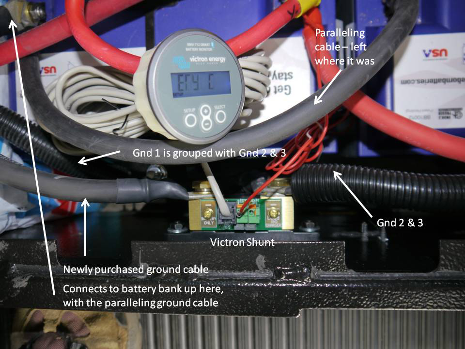
You can see I positioned the shunt just off centre, in order to make the ground cables all fit comfortably. The ground cable that comes from the coach into the battery box from the left side is in a plastic loom, as are the two ground cables that come from the coach into the battery box from the right side - and all are attached to the right post of the shunt. The ground cable on the left post of the shunt is NEW, and is not in a plastic loom. It hooks up directly to the negative post of the left battery and is the only external ground cable that connects to the battery bank.
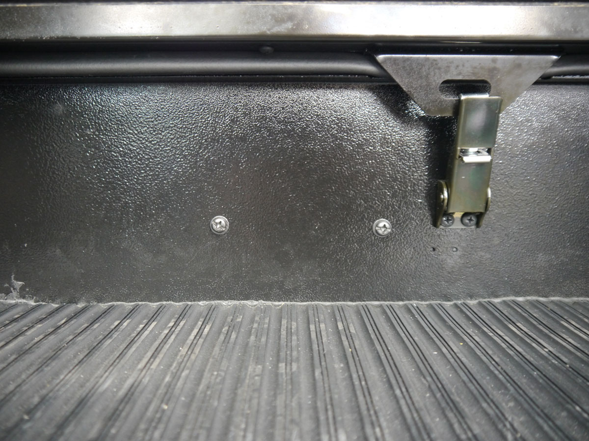
Here is a shot of the stair riser, or the front of the battery box, with the bolt heads that attach the Victron shunt to the inside of the step riser:
Aother shot of the completed installation - this one has the temperture probe lead also inserted into the shunt:
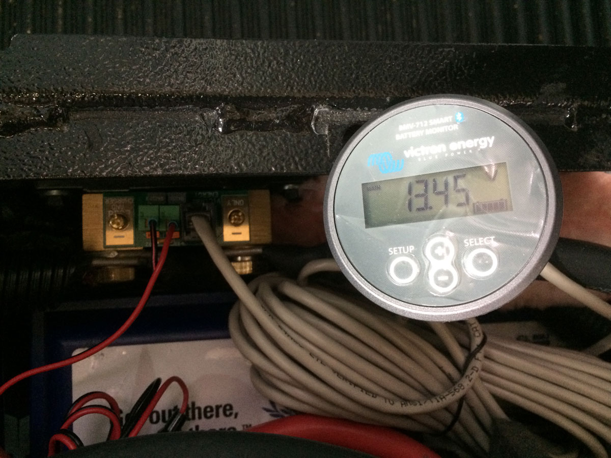
(So, I forgot to tell you that I purchased the temperature sensor as well. I wanted to keep an eye on the battery temperature, knowing that we were venturing out into the cold. It worked very well, and configuring the app to read this sensor was easy. Now, you are just reading the temperature of one of the positive battery posts - but I guess that is pretty close to internal battery temperture. I noticed that that the batteries start accepting a charge when my post temperture reaches -2 C.)
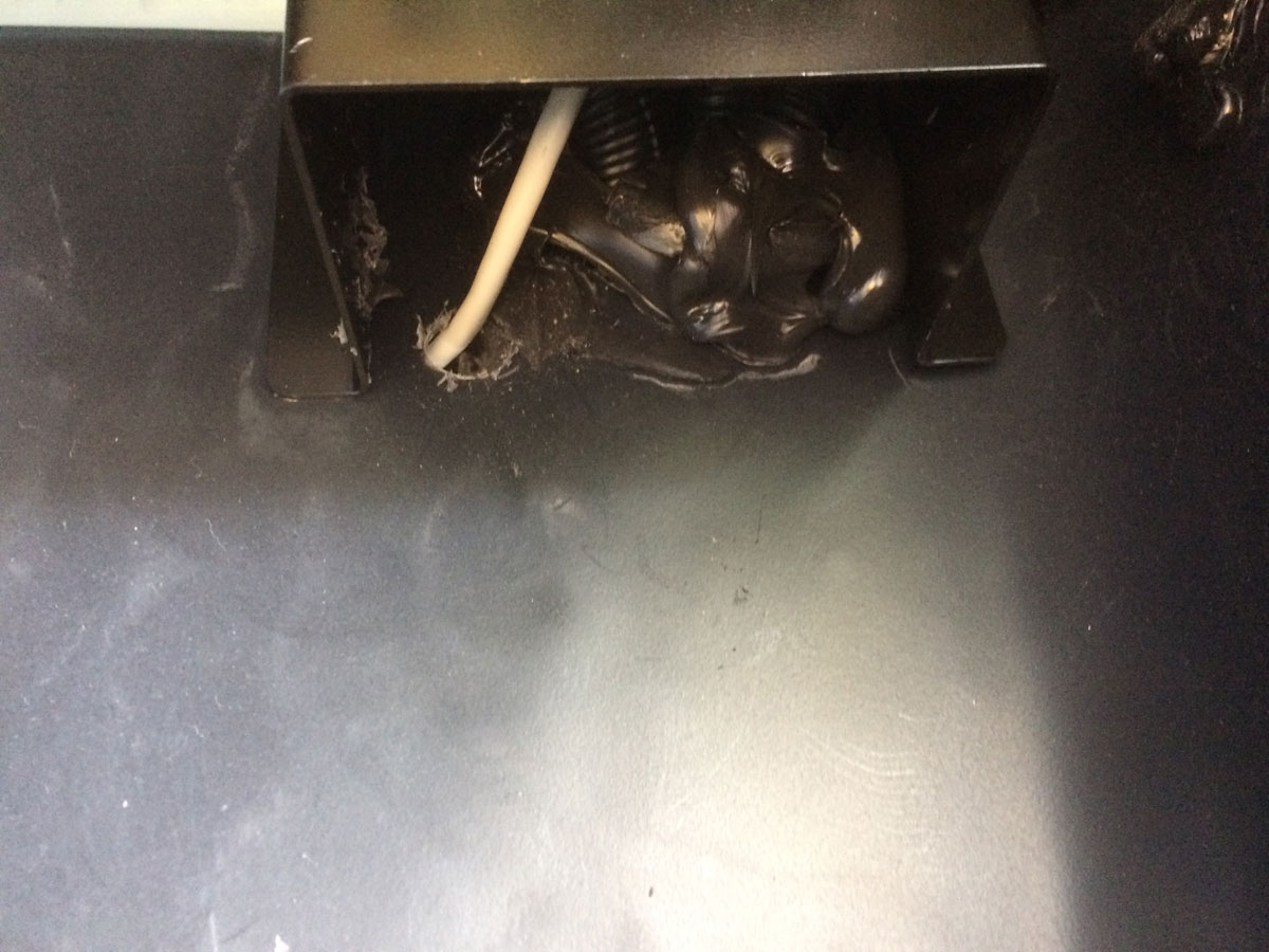
The Victron gauge install in the panel above the cooktop was a little more extensive than the EMS gauge install, but more or less the same idea. From the battery box I fed the BMV cable out through the left hand side cable entry, and drilled a hole in the neighboring locker near where the cables feeding the inverter can be found. (I filled the hole with silicon caulking to ensure the locker remained sealed.)
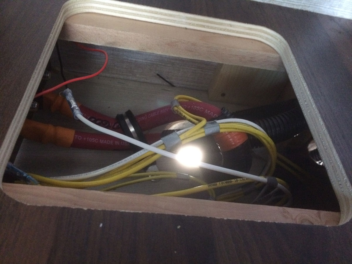
From there I fed the cable up through the protective guard and into the base of the sink cabinet, following the path that the cables from the inverter follow. (There is an access panel on the floor of the sink cabinet that makes this pretty straightforward.)
Once the cable was under the cabinet, I fed an electricians’s cable puller from the water heater area, under the fridge, under the cabinet with the pullout drawers, and then under the sink cabinet to the access panel area. Then, I pulled back the cable to the water heater area. Next, I used the same technique as I did on the EMS install - the trick here was to remove the cover panel in the cabinet above the cooktop, unplug the inverter com cable and the DC inputs for the tank heater switch, and get access to the space above the refrigerator from the hole in the side of the cabinet. I tried two or three ways to get an electrician’s cable puller into the area by the Truma water heater, and finally had success by starting the fishing expedition from on top of the refrigerator. By removing the three screws on the fridge control panel, the whole cover panel slid out and revealed the top of the fridge.
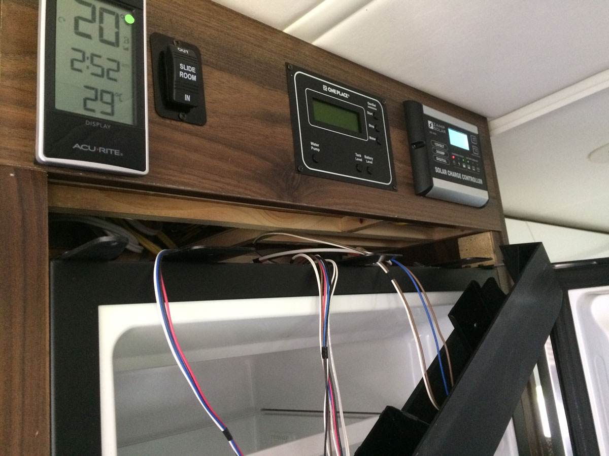
I inserted a cable fisher in the back right corner and went straight down the back right side of the fridge. The cable fisher popped out down by the water heater.
Here is a shot of where I started the electician’s cable puller down the back of the fridge:
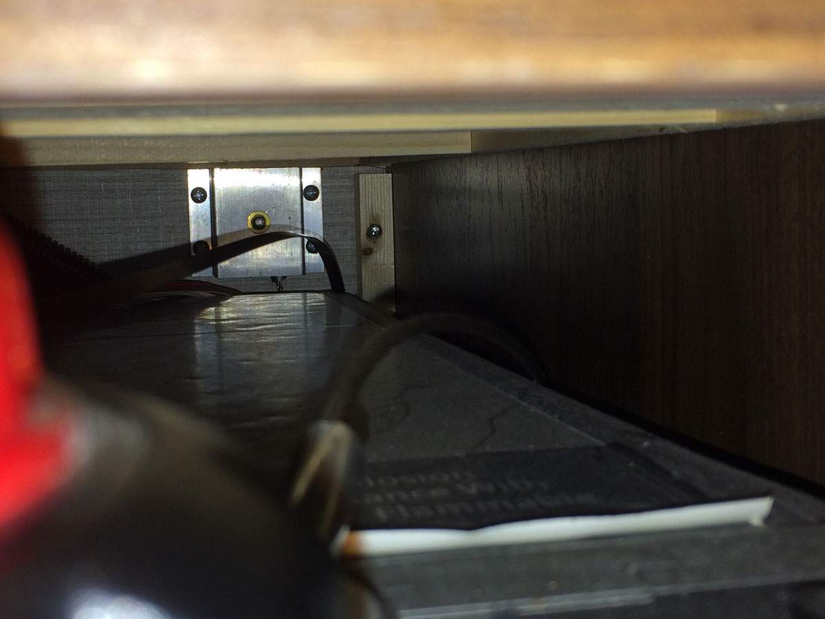
Once I got ahold of the BMV cable left in the water heater area, I pulled it up to the top of the fridge and then fed it into the area that the cabinet panel covers up.
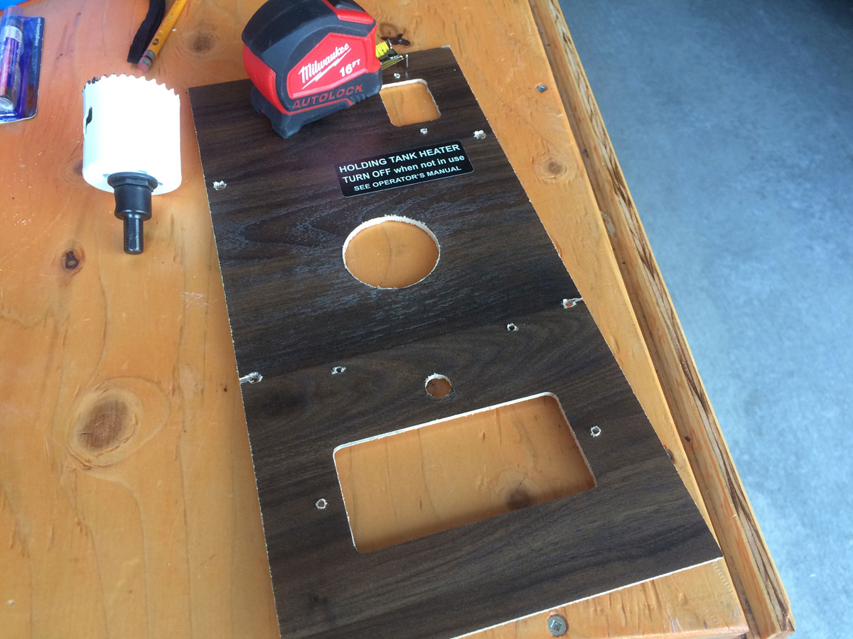
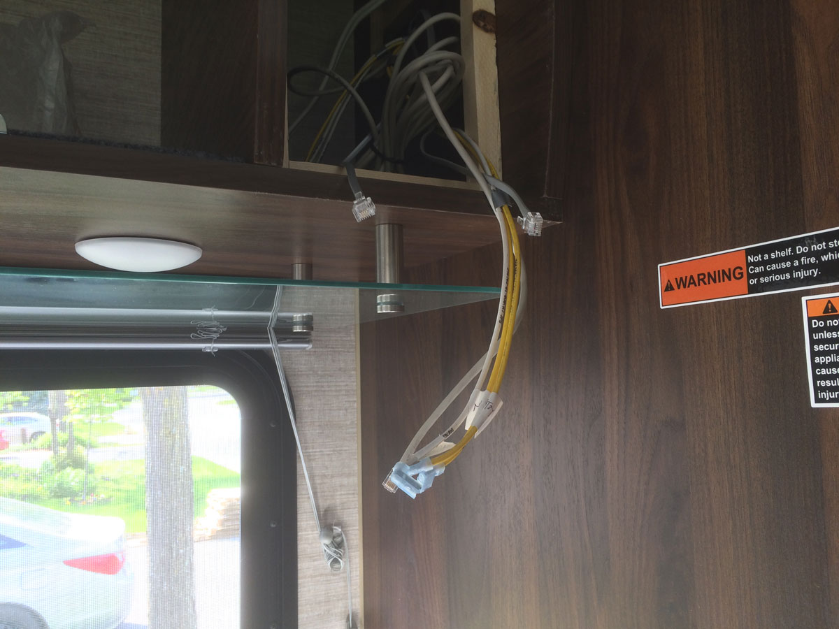
I did this gauge install in conjuction with the gauge install for the EMS, so I only had to do all of this once. Here are some photos of my gauge layout, hole location, the various cables that needed plugging into the gauges, and the end result: (Winnebago chewed up the face plate holes a bit, so I changed out the screws and added some washers to make things look a bit better)
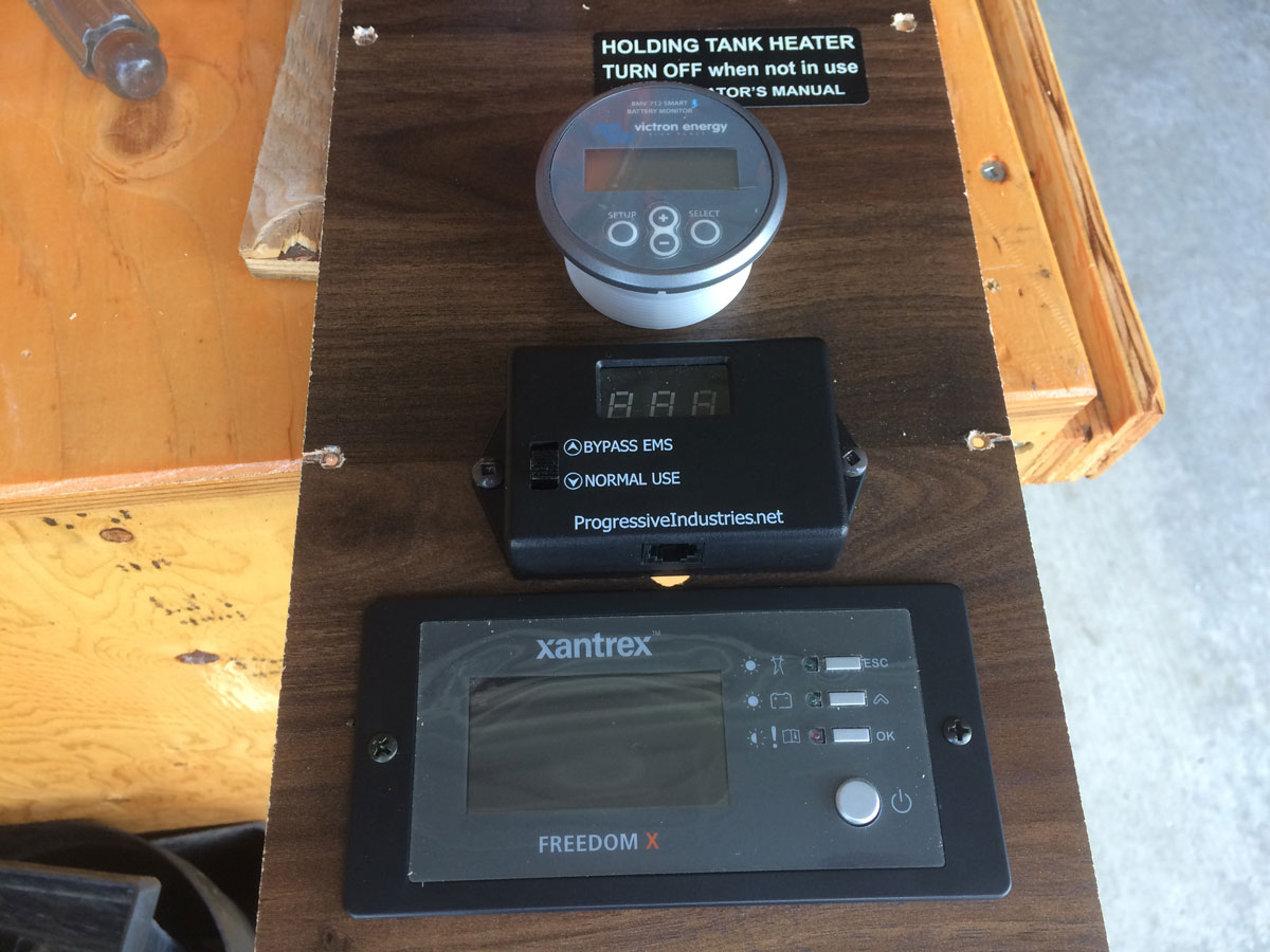
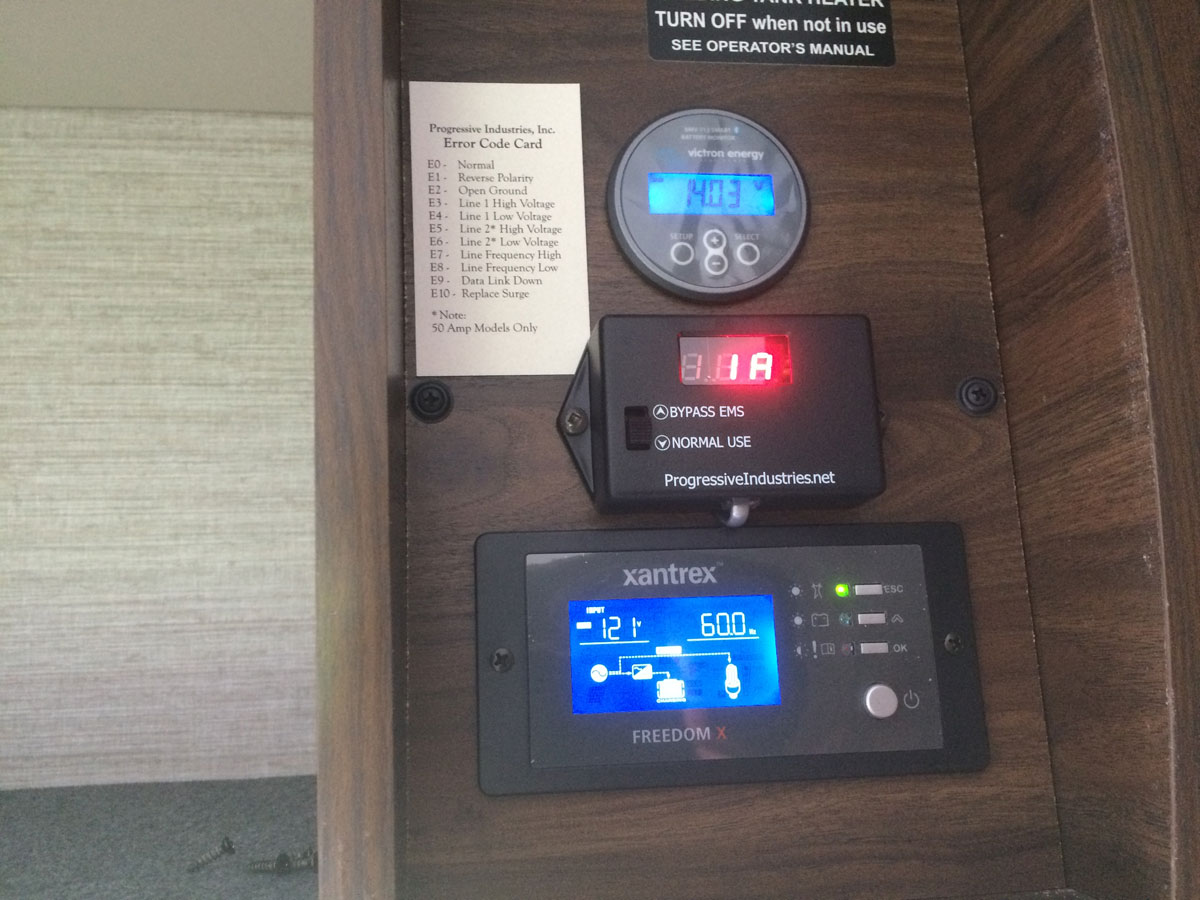
I gave the decision to purchase the 712 instead of the 702 considerable thought, and elected the 712 because of the Bluetooth connectivity feature. I wasn’t sure if it would be useful, but ended up being sold on the easy method of updating the operating software. And, it turns out, those software updates were very easy. During the install, the first time I opened the app, it asked if I wanted to update and get things going. Also, it turns out the decision go have the data on my phone was a very good idea. The phone app provides a very intuitive interface, and allows for quick retrieval of information at a glance. During the winter dry camping we do, I am frequently on the app monitoring our system heating mods to see how they are affecting battery temperatures (see “Cold Weather Capability” and “Lithium Battery Heater”).
As of 2023, I see that Victron now makes a “Smart Shunt” that does not require the dedicated monitor and its associated wiring. Instead, the shunt just connects to your device via bluetooth to send the battery data to your Victron app. If you don’t want the clutter of another gauge in your coach, this option might work for you. But… every now and then I do have connection difficulties using the bluetooth from Victron - it has not proven to be bullet proof - and I’ve been really glad that I can walk over the the gauge to have a look at what the batteries are doing. If the batteries are powered, the gauge is working. Just saying…
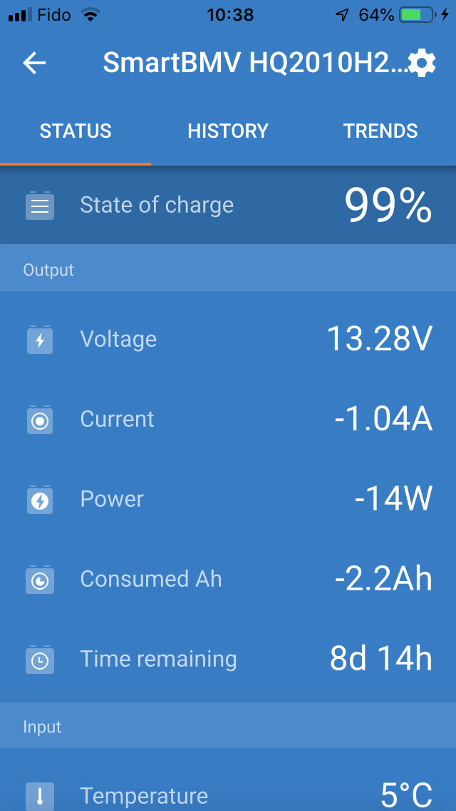
Here is what the app is showing you if you purchase the BMV 712 or the “Smart Shunt”:
All in all, we are very happy with this purchase. Working as advertised.